Ultra-wide-band wave-trapping antenna

A notch antenna and ultra-wideband technology, applied in the field of ultra-wideband notch antenna, can solve the problems of insufficient stopband bandwidth, poor filtering effect, frequency waste, etc., and achieve the effect of large space utilization, compact structure, and small overall size

Inactive Publication Date: 2014-04-30
UNIV OF ELECTRONICS SCI & TECH OF CHINA
View PDF2 Cites 12 Cited by
  • Summary
  • Abstract
  • Description
  • Claims
  • Application Information

AI Technical Summary

Problems solved by technology

[0006] However, at present, UWB notch antennas generally have the disadvantage of poor stopband selectivity of the notch, which cannot completely suppress the interference of other narrowband communication systems on UWB systems, and due to insufficient stopband bandwidth, the filtering effect is poor, and at the same time Many useful frequencies are also wasted
In addition, there is little mention of the impact of the notch structure on the notch bandwidth

Method used


Image

  • Ultra-wide-band wave-trapping antenna
  • Ultra-wide-band wave-trapping antenna
  • Ultra-wide-band wave-trapping antenna

Examples


Embodiment Construction

[0023] In order to make the object, technical solution and advantages of the present invention clearer, the present invention will be further described in detail below in conjunction with the accompanying drawings and embodiments. It should be understood that the specific embodiments described here are only used to explain the present invention, not to limit the present invention.

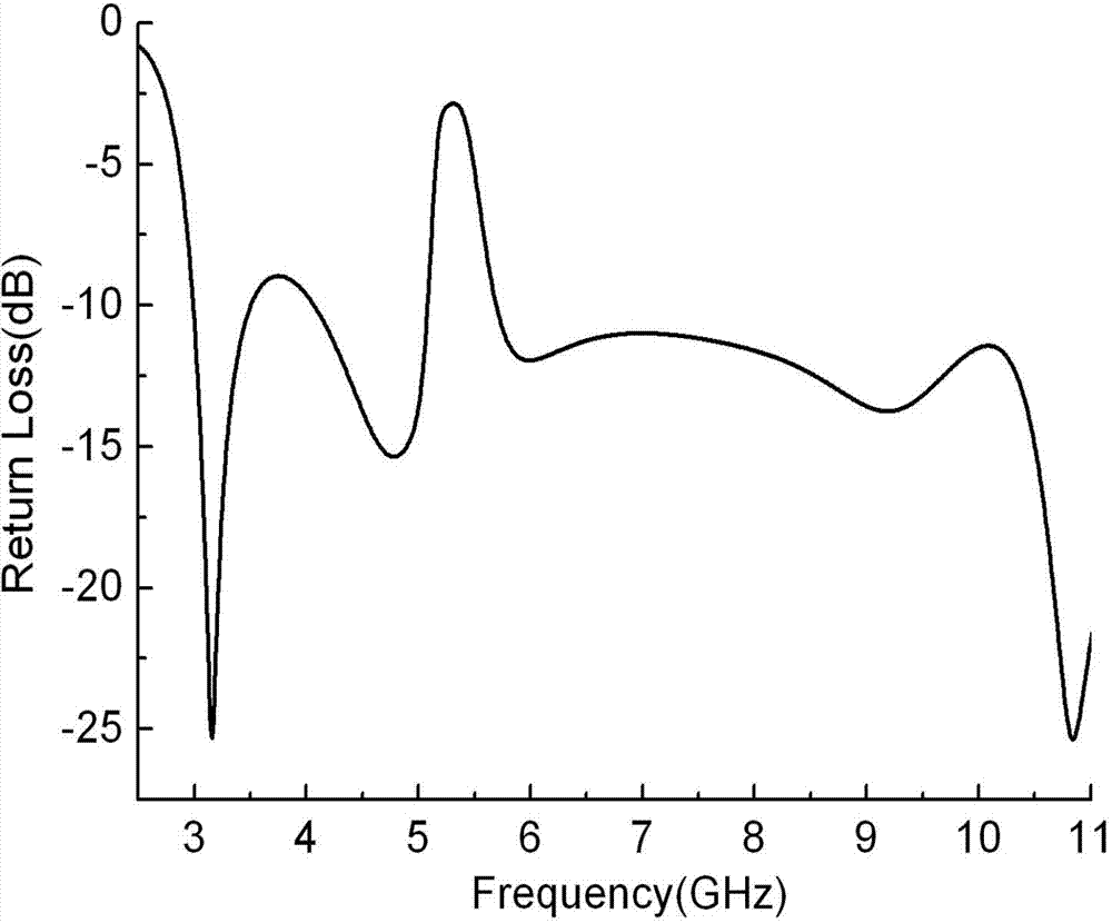
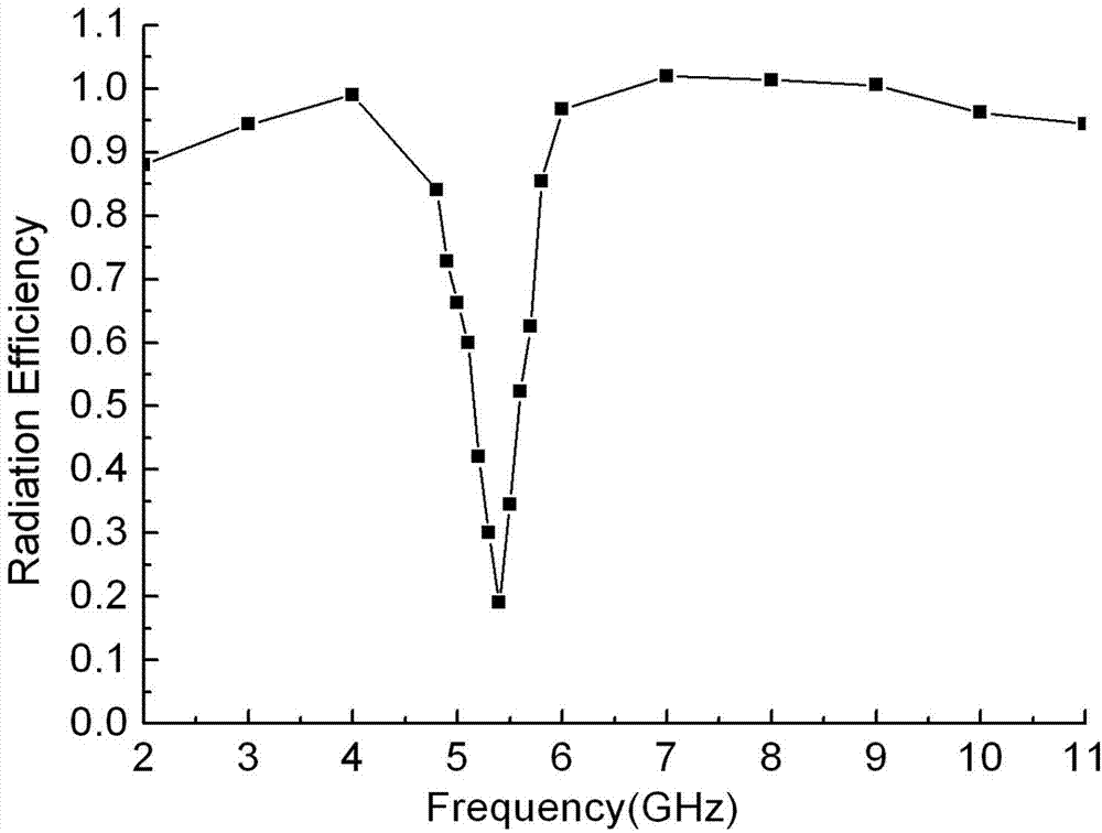
[0024] This embodiment is described by taking the notch stop band range of 5.15 GHz-5.825 GHz as an example to realize the UWB antenna.

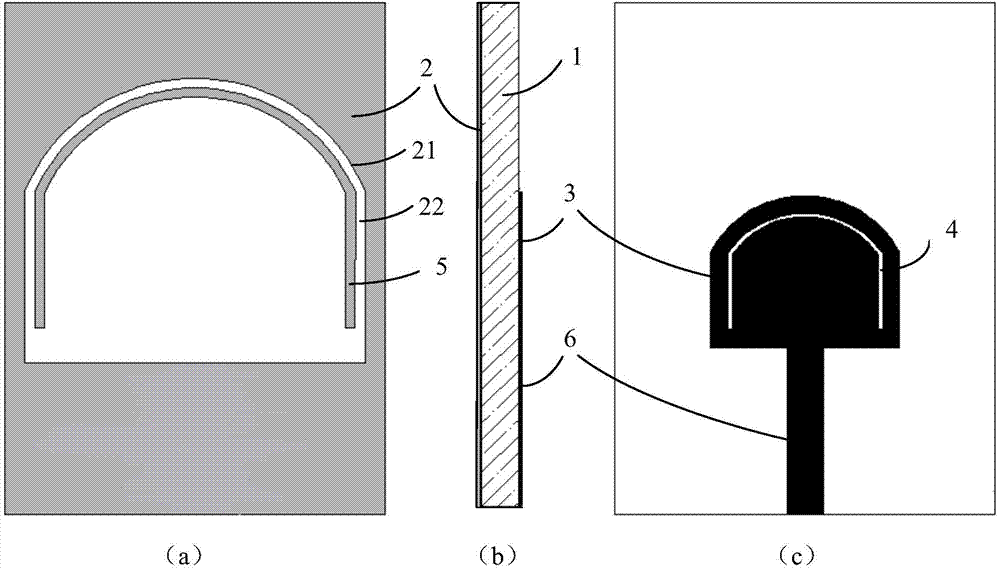
[0025] like figure 1 As shown in (a), 1(b), and 1(c), the UWB trap antenna in this embodiment includes a substrate 1, a floor 2 located on the back of the substrate 1, an inverted U-shaped parasitic open-circuit branch 5, and a substrate located on the front of the substrate 1. The antenna radiation patch 3, the antenna feeder 6 and the inverted U-shaped gap 4, wherein, the middle of the floor 2 has an inverted U-shaped wide groove 21, the top of the inverted U-...


PUM


Abstract

The invention discloses an ultra-wide-band wave-trapping antenna which comprises a base plate, a ground plate located on the back face of the base plate, a reversed-U-shaped parasitic open circuit branch knot, antenna radiation patches, antenna feeders and reversed-U-shaped gaps, wherein the antenna radiation patches, the antenna feeders and the reversed-U-shaped gaps are located on the front face of the base plate. A reversed-U-shaped wide slot is formed in the middle of the ground plate, the reversed-U-shaped parasitic open circuit branch knot is arranged inside the reversed-U-shaped wide slot, and coupling distances are reserved between reversed-U-shaped parasitic open circuit branch knot and the edges of the reversed-U-shaped wide slot. The antenna feeders are arranged on the middle lower portion of the base plate. The projections of the antenna radiation patches on the ground plate are located on the middle lower portion of the reversed-U-shaped wide slot, the reversed-U-shaped gaps are formed in the outer edges of the antenna radiation patches, and coupling distances are formed between the reversed-U-shaped gaps and the outer edges of the antenna radiation patches. A circle where the projections of the antenna radiation patches and the projections of the arc parts of the reversed-U-shaped gaps on the ground plate locate is concentric with the circle where the reversed-U-shaped wide slot and the arc part of the reversed-U-shaped parasitic open circuit branch knot locate. By loading the reversed-U-shaped gaps and the reversed-U-shaped parasitic open circuit branch knot simultaneously, the ultra-wide-band wave-trapping antenna has a wave trapping stop band which is good in rectangular degree, flat in stop band and controllable in band width.

Description

technical field [0001] The invention belongs to the technical field of antennas for wireless communication, and in particular relates to an ultra-wideband notch antenna with good stopband selectivity and good filtering effect. Background technique [0002] With the rapid development of science and technology and the increasing modernization and socialization of life, people continue to put forward newer and higher requirements for the application of electronic technology. Whether it is military communication or civil communication system, high-quality transmission of voice, text, image and multimedia information is required. While people are fully enjoying the convenience and fun brought by modern wireless communication, the available spectrum resources are becoming increasingly tense, and the original radio frequency spectrum has become very crowded. People urgently need a new technology to open up a new world for wireless communication. Ultra-wideband (Ultra-Wideband, UWB...

Claims


Application Information

Patent Timeline
Patent Type & Authority Applications(China)
IPC IPC(8): H01Q1/36H01Q1/38H01Q13/10
Inventor 尉旭波王超丁博张鸣霞廖家轩徐自强汪澎金龙田忠石玉
Owner UNIV OF ELECTRONICS SCI & TECH OF CHINA
Why Eureka
Try Eureka