Chained active power filter differentiation control method

A power filter and differential control technology, which is applied in active power filtering, electrical components, circuit devices, etc., can solve the problem that the voltage equalization effect is greatly affected by control parameters, increases system cost and volume, and is prone to overshoot and oscillation, etc. problems, to achieve the effect of convenient modular design and production, simple pressure equalization algorithm, and fast pressure equalization speed

Inactive Publication Date: 2014-04-30
陈峻岭
View PDF8 Cites 13 Cited by
  • Summary
  • Abstract
  • Description
  • Claims
  • Application Information

AI Technical Summary

Problems solved by technology

[0010] Chinese patent ZL200610113547.8 and Chinese patent 201110149521.X provide a chained APF DC capacitor voltage equalization method, setting a special DC capacitor voltage control algorithm for each chain link unit, the voltage equalization effect is greatly affected by the control parameters, and the voltage equalization process is easy overshoot and oscillation
Chinese patent 201010257367.3 and Chinese patent 200910238798.2 provide the use of additional circuits to realize the DC capacitor voltage balance of the chained APF, which increases the system cost and volume, and also increases the control complexity
These patents do not address switching devices with different switching frequencies

Method used


Image

  • Chained active power filter differentiation control method

Examples


Embodiment Construction

[0029] In order to make the objectives, technical solutions and advantages of the present invention clearer, the following further describes the present invention in detail with reference to the accompanying drawings and embodiments. It should be understood that the specific embodiments described herein are only used to explain the present invention, but not to limit the present invention.

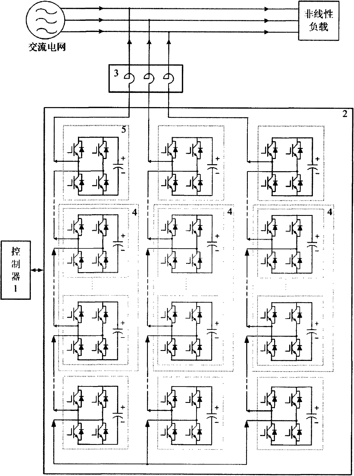
[0030] As shown in Figure 1:

[0031] The structure of a differential control method for a chain active power filter according to an embodiment of the present invention includes a controller 1, a chain multilevel inverter 2 for generating compensation voltage, and a Reactor 3 that generates compensation current and is connected to the grid. According to the needs of grid reactive power compensation and harmonic control, the controller 1 calculates the voltage that the chain-type multi-level inverter needs to generate, and the chain-type multi-level inverter 2 generates the compensation voltage...


PUM


Abstract

The invention relates to a chained active power filter differentiation control method. A cascade chain link unit is divided into a low-frequency module and a high-frequency module, the low-frequency module is used for generating a fundamental wave voltage required to be output by a chained multi-level inverter, and the high-frequency module is used for generating a voltage, without the fundamental wave voltage output by the low-frequency module, required to be output by the chained multi-level inverter. According to a period recycle mode, a plurality of chain link unit bodies selected from the cascade chain link unit serve as the high-frequency module. In the control period, the chain link unit body with the highest direct current capacitor voltage, the chain link unit body with the lowest direct current capacitor voltage, the chain link unit body with largest discharging to a direct current capacitor from a current pulse combination and the chain link unit body with largest charging to the direct current capacitor from the current pulse combination are found, pulses of the chain link unit body with the highest direct current capacitor voltage and pulses of the chain link unit body with the largest direct current capacitor discharging are exchanged, and pulses of the chain link unit body with the lowest direct current capacitor voltage and pulses of the chain link unit body with largest direct current capacitor charging are exchanged. According to the chained active power filter differentiation control method, the system switch losses can be remarkably reduced, and the balance effect and the compensation effect on the direct current capacitor voltages of the chain link unit bodies are guaranteed.

Description

Technical field [0001] The invention belongs to the technical field of power system reactive power compensation and harmonic control, and relates to a differential control method of a chain active power filter. Background technique [0002] With the development of power electronic technology, various non-linear power electronic devices have been widely used in power systems, industry, transportation, building automation and homes, and their device capacity is increasing and control methods are diversified. Voltage and current waveform distortions are becoming more and more serious, and harmonic pollution in the power grid is becoming more and more serious. Active power filter (APF) has become a hot spot in current research and application. Compared with traditional passive power filters, APF has the following advantages and characteristics: [0003] 1. With multiple compensation functions, it can not only compensate for various harmonics, but also dynamically compensate reactive ...

Claims


Application Information

Patent Timeline
Patent Type & Authority Applications(China)
IPC IPC(8): H02J3/01
CPCH02J3/01H02J3/1857Y02E40/22Y02E40/26Y02E40/40H02M1/12Y02E40/20H02M1/327H02M7/4835H02M7/219
Inventor 苑雪飞
Owner 陈峻岭
Why Eureka
Try Eureka