Multi-edge endmill

A technology of end mills and bottom edges, which is applied in the direction of milling cutters, forming cutters, milling machine equipment, etc., can solve problems such as lack of careful study, and achieve the effect of improving discharge

Active Publication Date: 2014-04-30
HITACHI TOOL ENG LTD
View PDF18 Cites 14 Cited by
  • Summary
  • Abstract
  • Description
  • Claims
  • Application Information

AI Technical Summary

Problems solved by technology

In paragraph 0013 of this patent document 1, it is described that the blank of the impeller is fixed on the rotating shaft, and the three-axis control of the rotating conical ball end mill is performed, and the numerical control is performed along the surface of the blade part to control the impeller. The technology of cutting the blade part, but for the tool itself, it has not carefully studied the design for processing

Method used


Image

  • Multi-edge endmill
  • Multi-edge endmill
  • Multi-edge endmill

Examples


Embodiment

[0198]Hereinafter, although an Example demonstrates this invention, this invention is not limited by the following Example.

experiment example 1

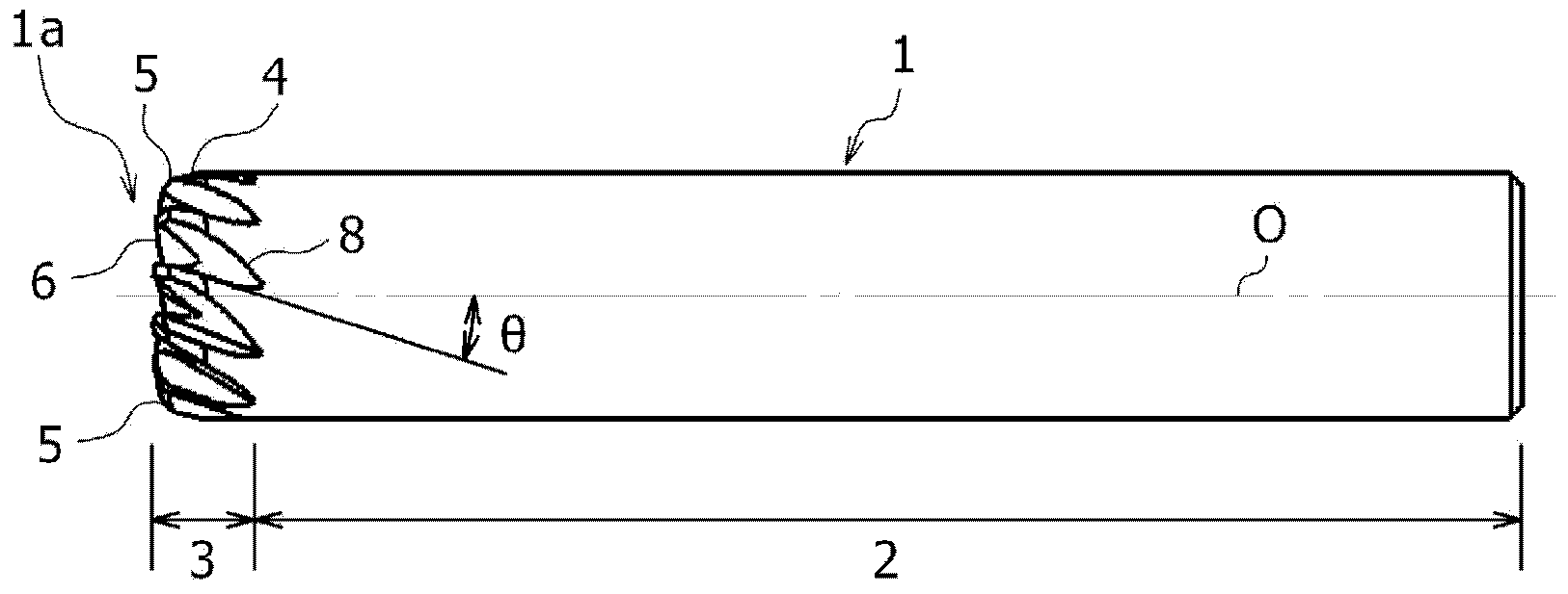
[0201] As described above, as one of the features of the multi-blade end mill 1 of the present invention, the radius cutting edge 5 is provided with the rake face 5 a of the radius cutting edge 5 forming a convex curved surface. In Experimental Example 1, an end mill of an example of the present invention (Example of the present invention 1) in which a rake face 5a is provided on a radius edge 5 was trial-manufactured. The block (aged) was mounted on a vertical three-axis machining center with an inclination angle of 10°, and the inclined surface (inclination angle: 10°) of the block was pulled. When the cumulative cutting distance reached 45 m, the state of wear of the cutting edge was visually observed.

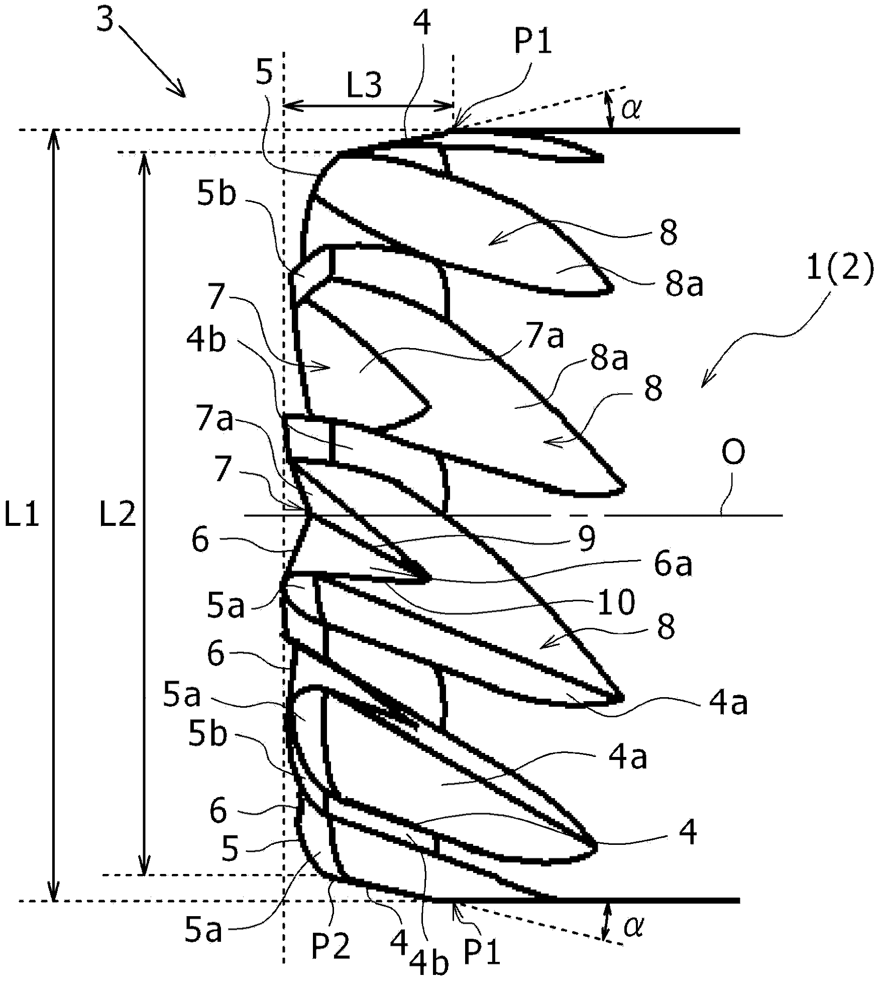
[0202] It should be noted that, as described above, in Example 1 of the present invention, the rake face 5a of the radius cutting edge 5 and the rake face 4a of the peripheral cutting edge 4 are formed to be gently convex curved surfaces, and the rake face 5a and The rake ...

experiment example 2

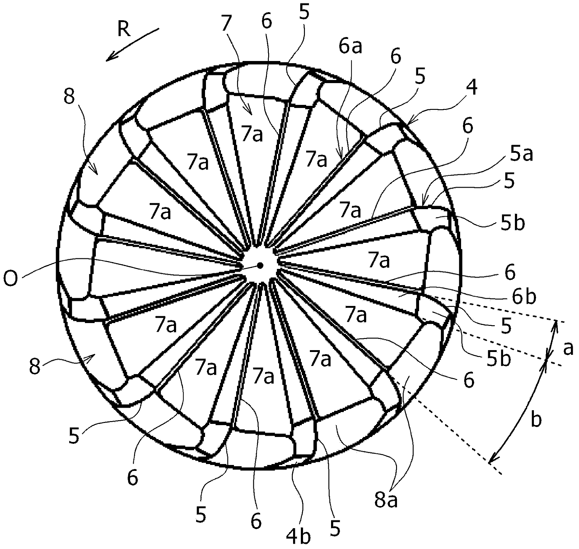
[0220] Next, multi-blade end mills with different numbers of blades, angle a of the width of the flank 6b of the bottom edge 6, and opening angle b of the notch 7 were trial-produced, that is, the volume (V) of the insert pocket CP per blade Different multi-blade end mills made of cemented carbide according to Example 2 of the present invention and Comparative Example 2. Then, the trial multi-blade end mill was mounted on a vertical three-axis machining center to perform high-feed cutting, and a cutting experiment was performed to confirm the wear state of the cutting edge and the occurrence of edge curling. Table 2 shows the specifications of the multi-blade end mills of Example 2 of the present invention and Comparative Example 2 used in Experimental Example 2. In addition, Comparative Example 2 is an end mill having a cutting edge structure similar to that of the multi-blade end mill disclosed in Patent Document 3. Furthermore, in the multi-blade end mills of Example 2 of ...


PUM


Abstract

To improve removal of chips generated when performing high feed processing of thin-walled materials such as impellers using a multi-edge endmill. In a multi-edge endmill (1) having a cutting edge part (3) provided with multiple cutting edges and flutes (8) formed between cutting edges that are adjacent in the direction of rotation around the tool axis (O), the rake face of the cutting edge is configured from: the rake face (6a) of an end cutting edge (6) from the tool axis (O) to the outer circumference of the shank (2); the adjacent rake face (5a) of a corner R edge (5) that forms a surface different from the rake face (6a) of the end cutting edge (6); and the adjacent rake face (4a) of a peripheral cutting edge (4) that forms a surface different from the rake face (5a) of the corner R edge (5). Between the rake face (6a) of an end cutting edge (6) and the flank (6b) of the end cutting edge (6) that is adjacent on the forward side thereof in the direction of rotation (R), a gash (7), which configures a space that is continuous with the flute (8), is formed, and one surface that configures the gash (7) also serves as the rake face (6a) of the end cutting edge (6).

Description

technical field [0001] The present invention relates to a machine tool that can be mounted on the machine tool when cutting with a three-axis or five-axis machine tool to manufacture thin-walled impellers or blades used in rotary mechanical devices such as turbochargers and superchargers. Improved multi-edge end mills equipped with multiple cutting edges for high-feed machining of blanks such as impellers. Background technique [0002] End milling is performed while fixing a difficult-to-cut alloy blank (difficult-to-cut material) made of Ni-based heat-resistant alloy such as Inconel (registered trademark) 718, stainless steel, or titanium alloy on the rotating shaft of the machine tool. Cutting tools such as knives are rotated, and multi-axis control is performed to perform various cutting processes such as rough machining, semi-finishing, and finishing on difficult-to-cut materials, thereby manufacturing thin-walled parts used in rotating machinery such as turbochargers an...

Claims


Application Information

Patent Timeline
Patent Type & Authority Applications(China)
IPC IPC(8): B23C5/10
CPCB23C2210/082B23C5/10B23C2210/209B23C2210/208B23C2210/0442B23C2215/44Y10T407/1948B23C5/12B23C2210/08B23C2210/32B23C2210/40
Inventor 马场诚平井纯一
Owner HITACHI TOOL ENG LTD
Why Eureka
Try Eureka