Novel rapid cooling hydrogen tank

A new type of cold hydrogen technology, which is applied in the field of gas-liquid fluid mixed heat transfer equipment, can solve the problems of increased heat transfer effect, ineffective effect, and prolonged operation cycle of hydrogenation equipment, so as to improve heat exchange efficiency and eliminate hot spots.

Active Publication Date: 2014-05-07
CHINA PETROLEUM & CHEM CORP +1
View PDF9 Cites 6 Cited by
  • Summary
  • Abstract
  • Description
  • Claims
  • Application Information

AI Technical Summary

Problems solved by technology

Due to the prolonged operation period of the hydrogenation unit, the flow state of the material in the initial stage and the final stage of the reaction changes greatly, and the material needs a certain flow rate to form a rotation. It is not advisable to enhanc

Method used


Image

  • Novel rapid cooling hydrogen tank
  • Novel rapid cooling hydrogen tank
  • Novel rapid cooling hydrogen tank

Examples


Example Embodiment

[0023] The structure and working effects of the present invention will be further described below in conjunction with the drawings.

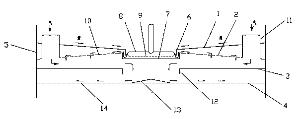
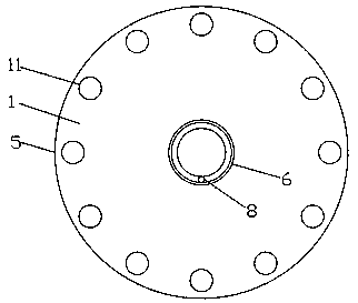
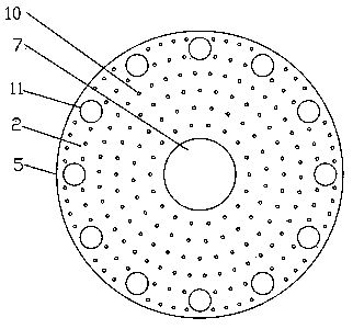
[0024] Such as figure 1 As shown, the main structure of the quench hydrogen tank of the present invention includes a liquid collecting plate 1, a drip plate 2, a partition 3, a redistribution sieve plate 4, and a reactor wall 5. The liquid collecting plate 1, the dripping plate 2, the partition 3, and the redistribution sieve plate 4 are all connected with the reactor wall 5 to form a multilayer plate structure.

[0025] The liquid collecting plate 1 is located at the uppermost layer. The liquid collecting plate 1 is a cone plate with a central opening, the cone opening faces downward, and the central opening is provided with a baffle tube 6. The baffle 6 has a cylindrical structure, and its upper edge is connected with the liquid collecting plate. The drip plate 2 is located under the drip plate 1. The drip plate 2 is a cone plate with an upward c...


PUM


Abstract

The invention discloses a novel rapid cooling hydrogen tank. The novel rapid cooling hydrogen tank comprises, from the upper part to the lower part, a liquid collecting plate, a liquid dropping plate, a separating plate, and a redistributing sieve plate; a center opening of the liquid collecting plate is provided with a traverse baffle; a center opening of the liquid dropping plate is provided with a liquid collecting groove; a cold hydrogen pipe coiled pipe is arranged in the liquid collecting groove; a center opening of the separating plate is provided with a mixing pipe; the center of the redistributing sieve plate is provided with a diversion cone; and the periphery of the diversion cone is provided with small holes. The novel rapid cooling hydrogen tank is provided with the liquid collecting groove, and the liquid collecting groove is used for collecting liquid phase materials of an upper bed layer; the cold hydrogen pipe is arranged in the liquid phase materials in the liquid collecting groove in a coiled manner, cold hydrogen is sprayed out from the cold hydrogen pipe so as to stir and bubble the liquid phase materials, the relatively high temperature difference of the cold hydrogen and the liquid phase materials is used for enhancing gas-liquid heat transferring, heat is transferred from the liquid phase materials to the cold hydrogen, and then the cold hydrogen is mixed with oil gas for heat transferring, so that heat exchange efficiency of the novel rapid cooling hydrogen tank is increased greatly.

Description

technical field [0001] The invention relates to a gas-liquid fluid mixing heat transfer equipment flowing downwards in a petrochemical process, more specifically, it is used in a fixed-bed hydrogenation reactor in a petroleum processing process to make cold hydrogen and hydrocarbon reactants and heat Quenching hydrogen tank with hydrogen fully mixed. Background technique [0002] Due to the increasingly stringent global environmental protection regulations, the issue of sulfur content in petroleum products has attracted much attention. In response to the problem of reducing sulfur content, major oil companies in the world have made many efforts. Hydrogenation technology is an essential technology in the process of clean fuel production. Therefore, like hydrogenation catalysts and hydrogenation processes, the performance and design of hydrogenation reactor systems have naturally received the same attention from the industry. Internals are an important part of the reactor sy...

Claims


Application Information

Patent Timeline
IPC IPC(8): B01J8/02B01F13/02B01F3/04C10G49/00B01F33/40
Inventor 李经伟李欣陈新彭德强齐慧敏刘杰
Owner CHINA PETROLEUM & CHEM CORP
Why Eureka
Try Eureka