Supercharge Your Innovation With Domain-Expert AI Agents!

Counter-rotating end milling cutter

A technology of reverse rotation and end milling cutter, which is applied in the direction of milling cutters, milling machine equipment, manufacturing tools, etc., can solve the problems of milling cutters becoming blunt, machining cutting amount not meeting processing needs, and increasing production costs, etc., to achieve greater The effect of processing cutting amount, reducing processing cost and improving work efficiency

Inactive Publication Date: 2014-05-07
昆山华星模具导向件有限公司
View PDF0 Cites 3 Cited by
  • Summary
  • Abstract
  • Description
  • Claims
  • Application Information

AI Technical Summary

Problems solved by technology

[0002] With the increasing requirements for parts processing in the aerospace, automobile and machine tool manufacturing industries, milling cutters have become important milling tools in the aerospace, automobile and machine tool manufacturing industries. They are mainly used to process planes, steps and grooves on milling machines , forming surfaces and cutting workpieces, etc. The commonly used type of milling cutters is end mills, which are used to process grooves and stepped surfaces, etc. The cylindrical surface and end face of end mills have cutting edges, which can be cut at the same time during work. It can also be cut separately. The commonly used end mill is a down milling cutter, that is, when the milling cutter and the workpiece move relative to each other, the feed direction of the workpiece is the same as the rotation direction of the milling cutter. When using a down milling cutter to process the workpiece, if the workpiece The hardness of the surface is high, and the teeth of the milling cutter are susceptible to greater impact. Over time, the milling cutter tends to become blunt. When it is necessary to increase the amount of machining and cutting, it does not meet the processing requirements, which affects the processing efficiency, and the utilization of the blade of the milling cutter The efficiency is low, usually only 3 of the 6 cutting edges of the blade are used, which cannot make full use of the blade, wasting resources and increasing production costs

Method used


Image

  • Counter-rotating end milling cutter
  • Counter-rotating end milling cutter
  • Counter-rotating end milling cutter

Examples


Embodiment Construction

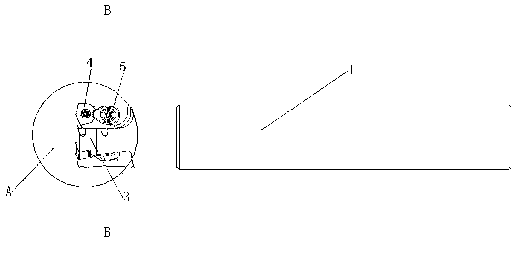
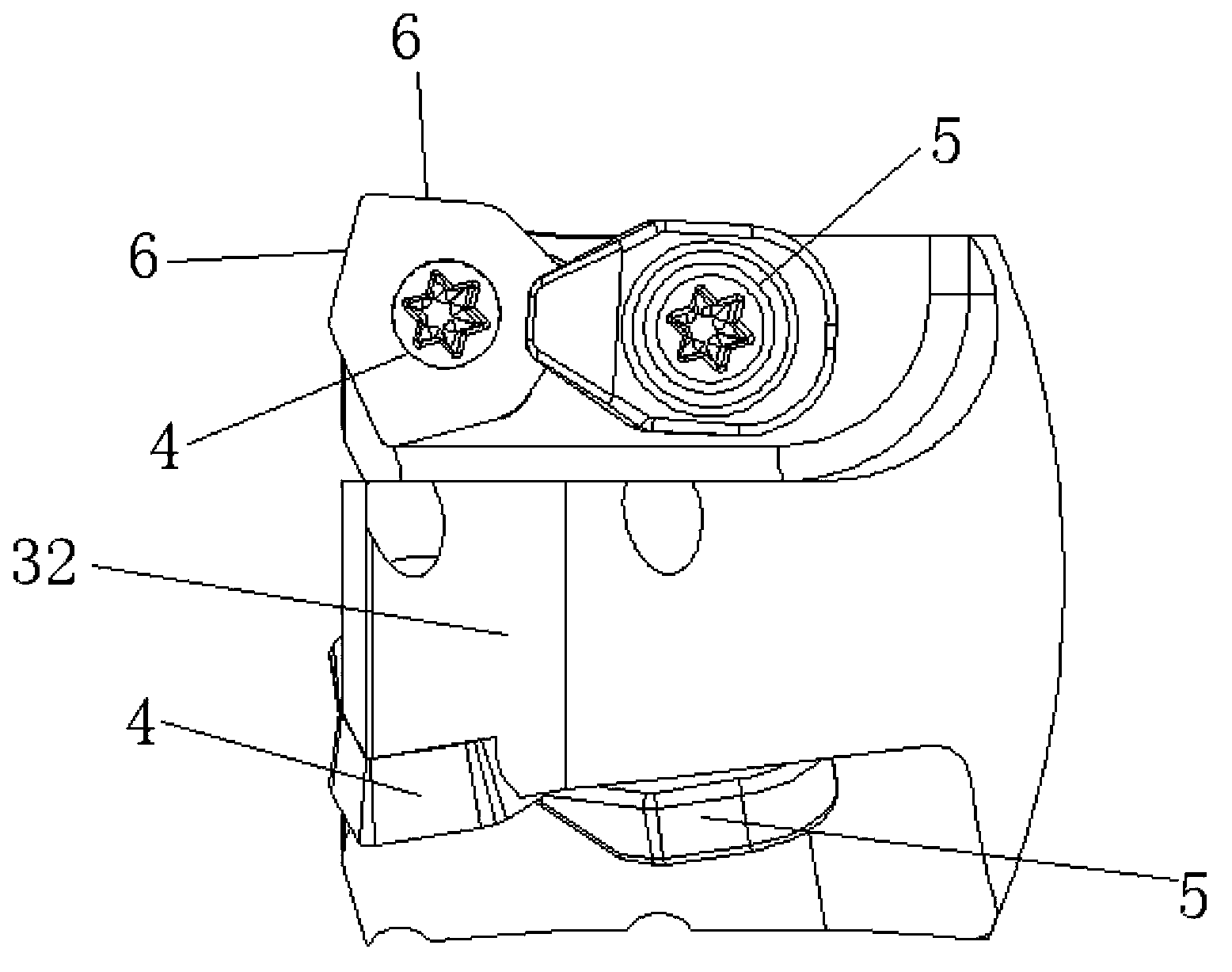
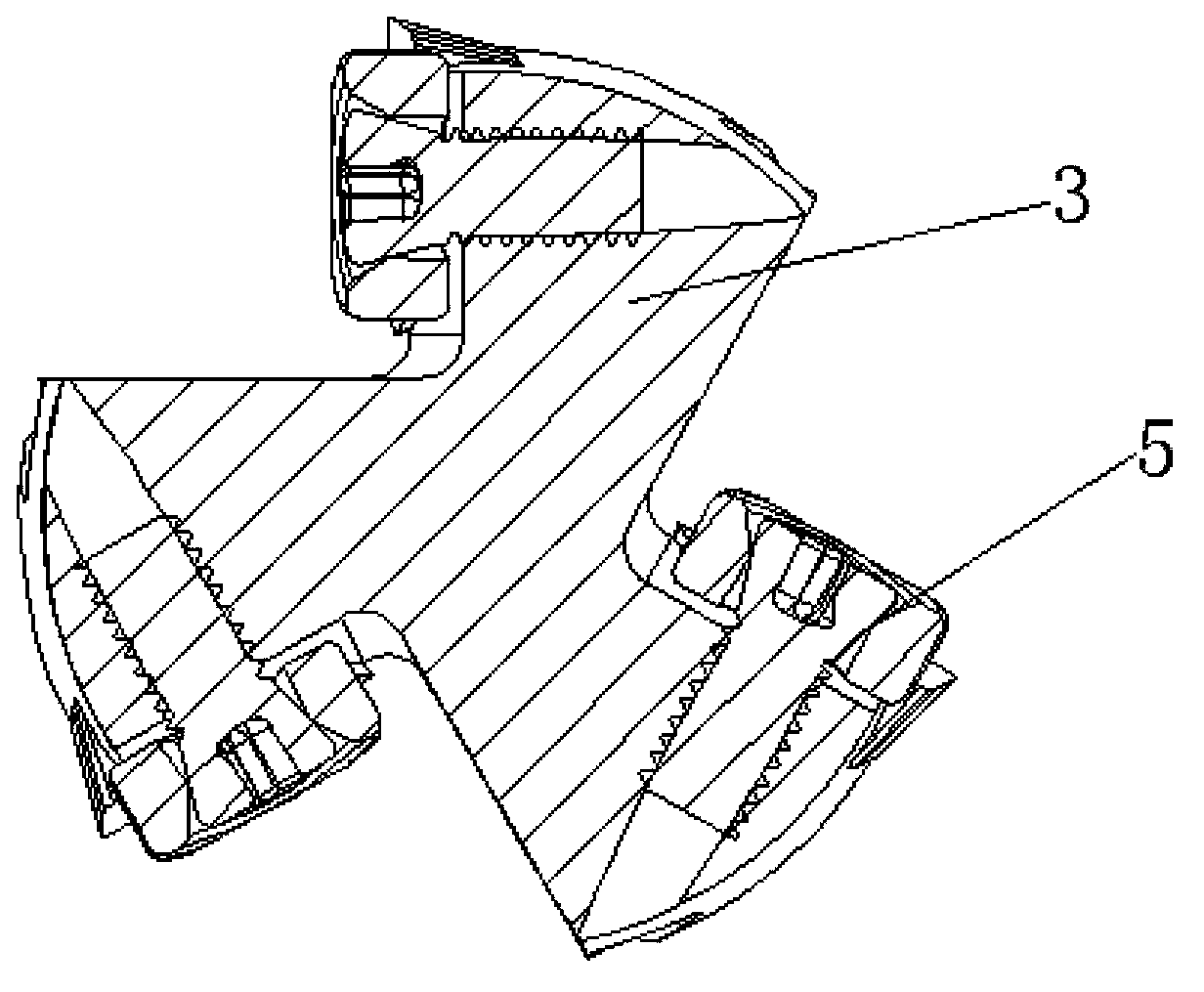
[0023] Such as figure 1 , figure 2 , image 3 , Figure 4 with Figure 5 As shown, a counter-rotating end mill includes a cylindrical shank 1, a plurality of grooves 2 are arranged at intervals around one end of the shank, and a ridge 3 is formed between two adjacent grooves. The axial direction of the shank is at a certain helical angle to the ridge, and the helical direction of the ridge is opposite to the feed direction of the workpiece to be processed. A blade 4 and a pressing plate 5 are fixedly arranged on one side of the ridge, and the blade It consists of a number of cutting edges 6 that are connected head to tail in sequence, wherein two adjacent cutting edges protrude from the end surface 31 of the ridge and the side surface 32 respectively, and the two cutting edges are respectively in the shape of the end surface and the side surface of the ridge. At a certain angle, the pressure plate is located between the blade and the handle, and the pressure plate is part...


PUM


Abstract

The invention discloses a counter-rotating end milling cutter. The counter-rotating end milling cutter comprises a cylindrical handle part, wherein a plurality of grooves are arranged at the peripheral side at one end of the handle part at intervals; a convex ridge is formed between the two adjacent grooves; the convex ridge forms a certain spiral angle along the axial direction of the handle part; the spiral direction of the convex ridge is reverse to the feeding direction of a workpiece to be processed; a blade and a pressure plate are fixedly arranged at one side of the convex ridge in sequence; the blade comprises a plurality of cutting edges which are connected from the beginning to the end in sequence, wherein the adjacent two cutting edges respectively extend out of the end surface and the peripheral side surface of the convex ridge; the two cutting edges respectively form a certain angle with the end surface and the peripheral side surface of the convex ridge; the pressure plate is arranged between the blade and the handle; and the pressure plate is partially arranged on the outer surface, back to one side of the convex ridge, of the blade. The counter-rotating end milling cutter breaks through a normal working mode of the end milling cutter to generate large cutting force, so that the processing cutting output of the end milling cutter can be effectively increased, the blade of the end milling cutter can be sufficiently utilized, and the working efficiency is improved. Meanwhile, the resources are saved, so that the processing cost can be effectively reduced.

Description

technical field [0001] The invention relates to a milling cutter, in particular to a counter-rotating end milling cutter, which is suitable for cutting workpieces with high surface hardness or too rough surface. Background technique [0002] With the increasing requirements for parts processing in the aerospace, automobile and machine tool manufacturing industries, milling cutters have become important milling tools in the aerospace, automobile and machine tool manufacturing industries. They are mainly used to process planes, steps and grooves on milling machines , forming surfaces and cutting workpieces, etc. The commonly used type of milling cutters is end mills, which are used to process grooves and stepped surfaces, etc. The cylindrical surface and end face of end mills have cutting edges, which can be cut at the same time during work. It can also be cut separately. The commonly used end mill is a down milling cutter, that is, when the milling cutter and the workpiece mo...

Claims


Application Information

Patent Timeline
IPC IPC(8): B23C5/10B23C5/20
Inventor 吴兆宁
Owner 昆山华星模具导向件有限公司
Features
  • R&D
  • Intellectual Property
  • Life Sciences
  • Materials
  • Tech Scout
  • Unparalleled Data Quality
  • Higher Quality Content
  • 60% Fewer Hallucinations
Learn More