Control oil line of variable valve timing system

A valve timing and oil circuit control technology, which is applied to non-mechanically actuated valves, engine components, machines/engines, etc. Crossover is not independent and other problems, to achieve the effect of short control oil circuit layout, reduce oil pumping capacity, and shorten oil pumping time

Active Publication Date: 2014-05-07
CHONGQING CHANGAN AUTOMOBILE CO LTD
View PDF5 Cites 9 Cited by
  • Summary
  • Abstract
  • Description
  • Claims
  • Application Information

AI Technical Summary

Problems solved by technology

For the current engine with variable valve timing technology, the oil control valve is basically installed on both sides of the cylinder head or on the front cover. The oil supply circuits of the components are not independent, and affect and restrict each other, which eventually leads to poor response of the variable valve timing mechanism and low phase adjustment speed, which limits the improvement of engine performance

Method used


Image

  • Control oil line of variable valve timing system
  • Control oil line of variable valve timing system
  • Control oil line of variable valve timing system

Examples


Embodiment Construction

[0020] The present invention will be further explained below in conjunction with the drawings:

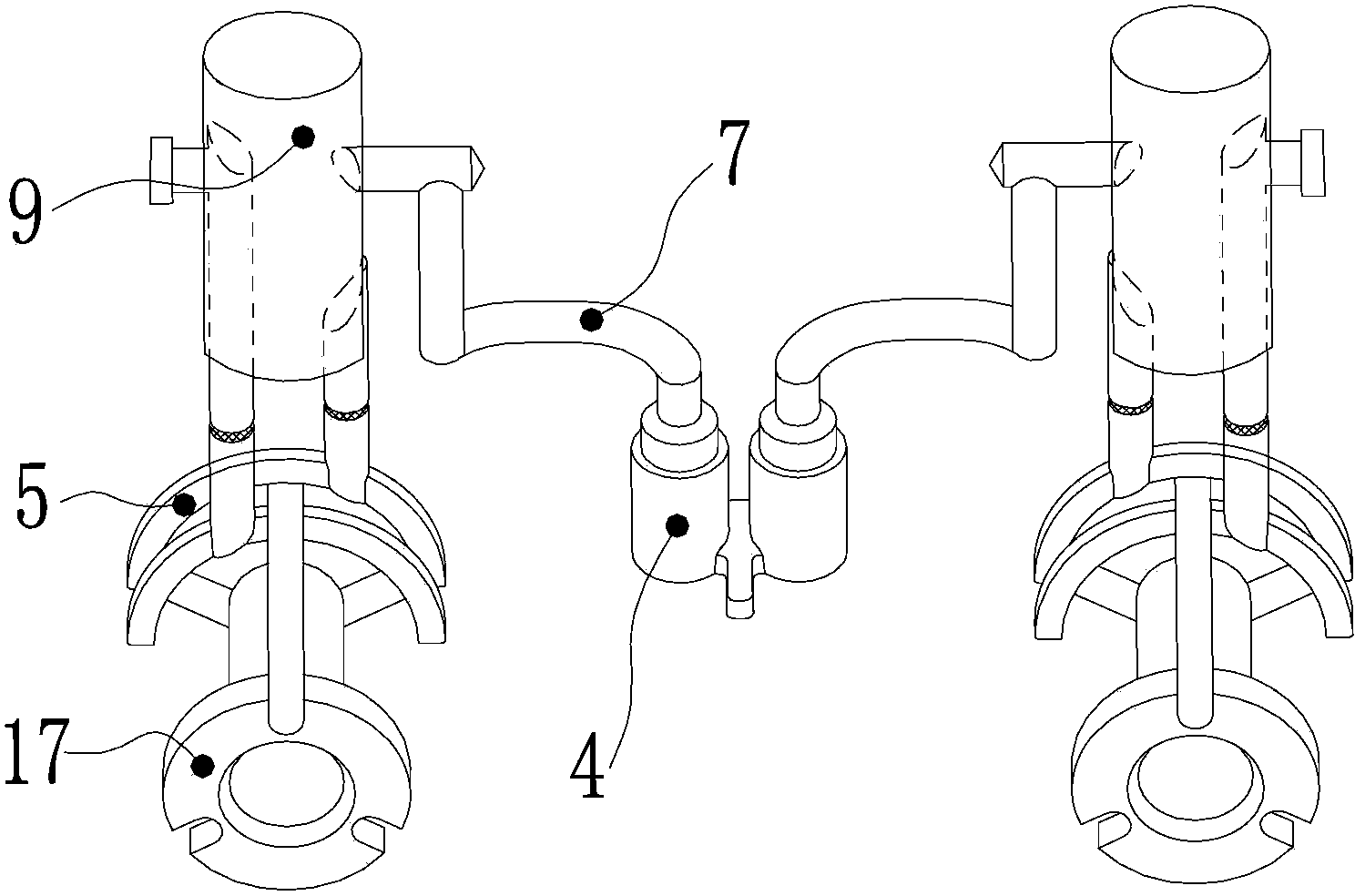
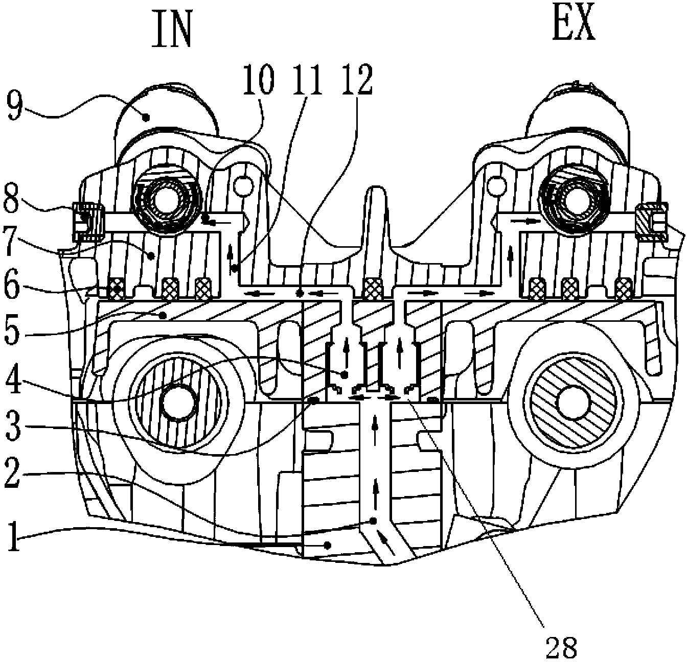
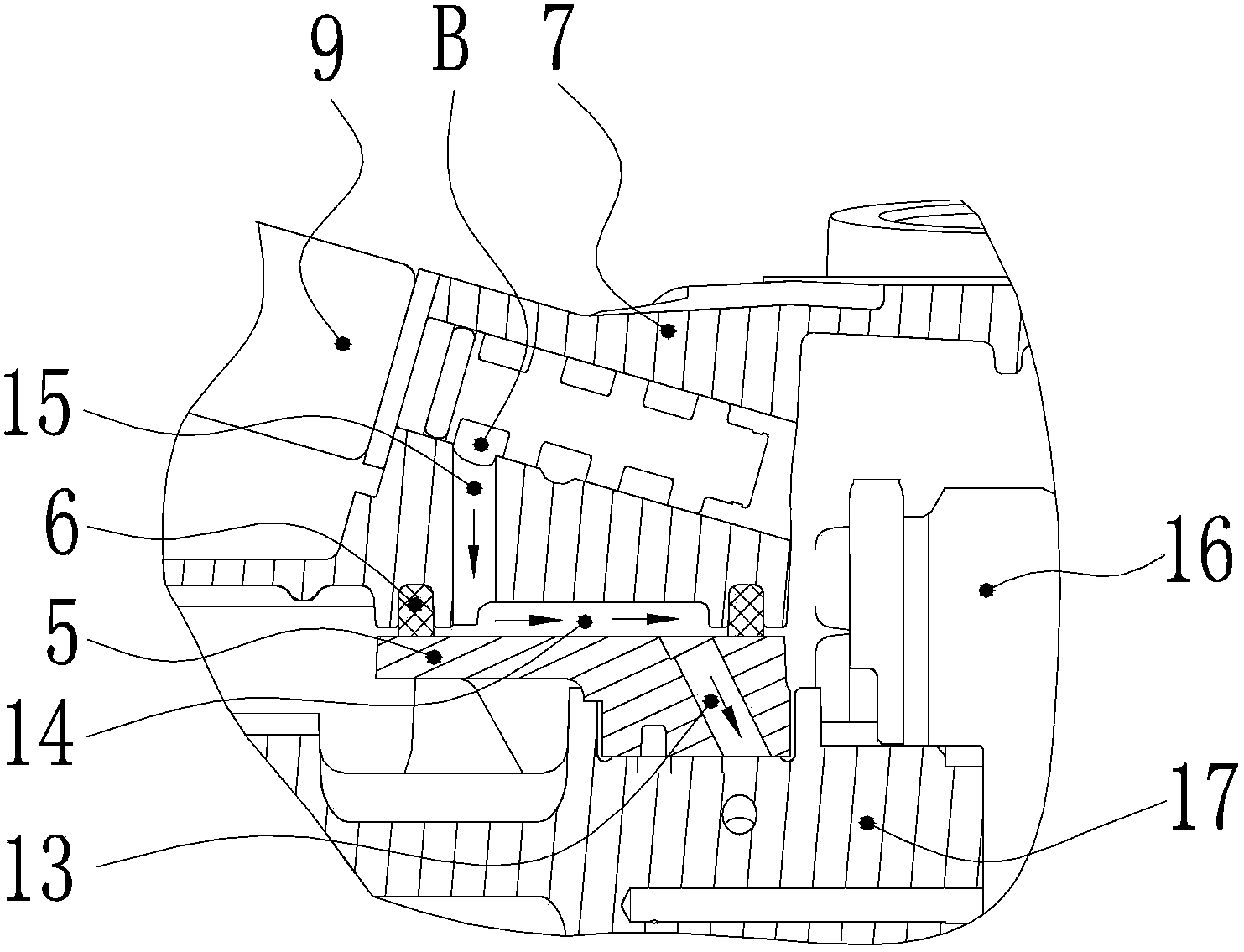
[0021] See Figure 1 to Figure 5 As shown, the control oil circuit of the variable valve timing system includes the intake and exhaust valve variable timing oil circuits. The inlet and exhaust valve variable timing oil circuits are respectively arranged in the cylinder head 1. The outlet of the main oil passage 2 is connected. The variable timing oil passages of the intake and exhaust valves and the exhaust valve variable timing oil passages have the same structure, which are symmetrically distributed on the camshaft bearing cover 5, camshaft 17 and cylinder head cover 7 ; From the front of the engine, the left side is the variable timing oil circuit of the intake valve, and the right side corresponds to the variable timing oil circuit of the exhaust valve.

[0022] The variable timing oil circuit of the intake valve includes a mounting hole for the oil control valve 9 arranged in the ...


PUM


Abstract

The invention discloses a control oil line of a variable valve timing system. The control oil line of the variable valve timing system comprises an intake valve variable timing oil line and an exhaust valve variable timing oil line. An inlet of the intake valve variable timing oil line and an inlet of the exhaust valve variable timing oil line are communicated with an outlet of a main oil gallery arranged in a cylinder head. The intake valve variable timing oil line and the exhaust valve variable timing oil line are distributed on a camshaft bearing cap, a camshaft and a cylinder head cover in a bilateral symmetry mode. Engine oil enters the control oil line through an oil gallery one-way valve, flows through the cylinder head cover and then reaches an engine oil control valve. When the engine oil flows out of an oil port A of the engine oil control valve, the engine oil flows through the cylinder head cover, the camshaft bearing cap and the camshaft in sequence and reaches a front oil cavity of a phaser finally. At this time, the engine oil in a rear oil cavity of the phaser flows out, flows through the camshaft, the camshaft bearing cap and the cylinder head cover in sequence, reaches an oil port B of the engine oil control valve finally and then is discharged through an oil port T of the engine oil control valve. According to the control oil line of the variable valve timing system, the oil line is shortened, so that loss of oil line pressure is reduced, and the performance of an engine is improved; moreover, the structure is simple and reasonable, so that the spatial arrangement of the engine is compact.

Description

Technical field [0001] The invention belongs to a gasoline engine with variable valve timing, and in particular relates to a control oil circuit of a variable valve timing system. Background technique [0002] Variable valve timing technology can reduce engine pumping loss, accelerate intake speed, improve mixture quality, change residual exhaust gas coefficient, increase intake efficiency, and ultimately improve engine combustion process, thereby increasing engine low-end torque and high-speed power , Reduce HC, NOx emissions, higher dilution rate can get better fuel economy. [0003] Since there are many types of variable valve timing mechanisms, the system oil circuit arrangements implemented by various mechanisms are different, and the performance of the variable valve timing mechanism is greatly affected by the system oil circuit arrangement. For engines with variable valve timing technology, the oil control valve is basically installed on both sides of the cylinder head or o...

Claims


Application Information

Patent Timeline
Patent Type & Authority Applications(China)
IPC IPC(8): F01L1/34F01L9/02F01L9/10
Inventor 张云富李春余训蒋树徽朱玉明乔艳军
Owner CHONGQING CHANGAN AUTOMOBILE CO LTD
Why Eureka
Try Eureka