Peak detection system and method for Hall gear sensor chip

A sensor chip, peak detection technology, applied in the peak detection system of the Hall gear sensor chip, the peak detection system, and the peak detection field of the Hall gear sensor chip, which can solve the problems of missed detection and longer response time of the peak detector. , to achieve accurate detection, avoid voltage peak signal attenuation, and avoid peak data errors

Inactive Publication Date: 2014-05-07
赛卓电子科技(上海)股份有限公司
View PDF3 Cites 2 Cited by
  • Summary
  • Abstract
  • Description
  • Claims
  • Application Information

AI Technical Summary

Problems solved by technology

If the capacitance is increased to reduce the impact of leakage, the response time of the peak detector will be longer, and it may cause missed detection in the case of high frequency operation.

Method used


Image

  • Peak detection system and method for Hall gear sensor chip
  • Peak detection system and method for Hall gear sensor chip
  • Peak detection system and method for Hall gear sensor chip

Examples


Embodiment 1

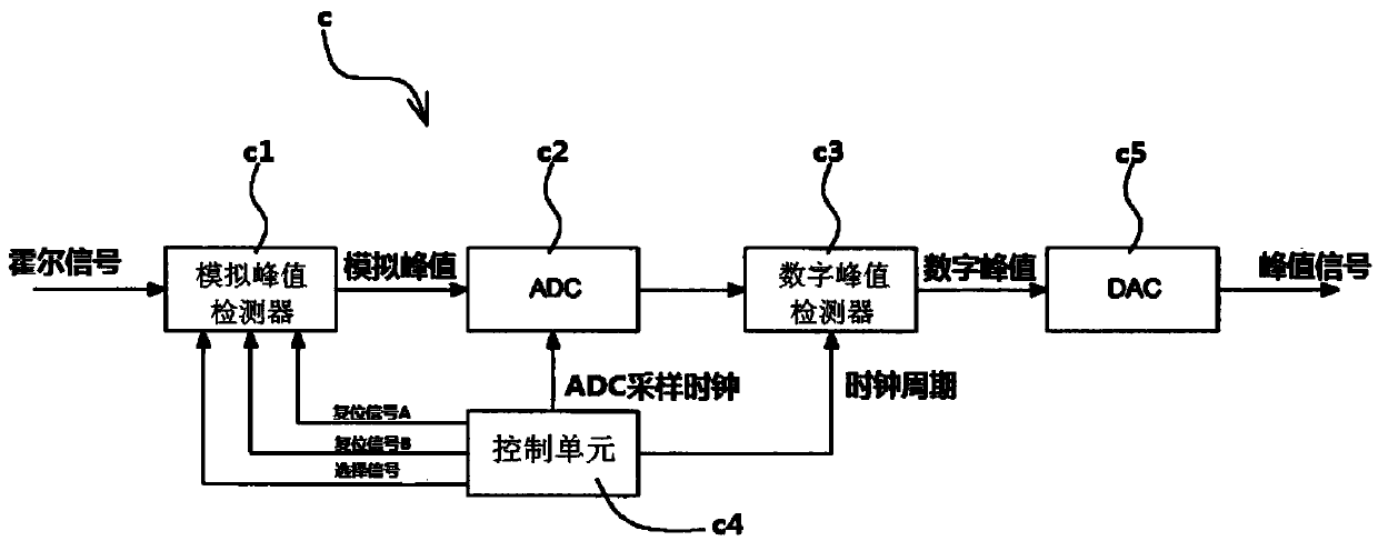
[0054] see image 3 , the present invention discloses a peak detection system applied to a Hall gear sensor chip, the peak detection system includes: an analog peak detector c1, an analog-to-digital converter c2, a digital peak detector c3, a control unit c4 and a digital-analog converter c5.

[0055] The analog peak detector c1 receives the Hall signal and detects the peak value of the Hall signal according to its own clock frequency. Since the clock frequency of the analog peak detector c1 is relatively fast, there is no need to use a large capacitor to avoid voltage attenuation caused by long-term storage, so the analog peak detector c1 can have a fast response frequency.

[0056] The analog-to-digital converter c2 converts the analog peak signal output by the analog peak detector c1 into a digital signal and inputs it to the digital peak detector c3. low) to detect digital peaks.

[0057] The control unit c4 generates various control signals such as selection signal, re...

Embodiment 2

[0062] The invention also discloses a peak detection method applied to the Hall gear sensor chip, which can be combined with image 3 , the peak detection method includes (the execution sequence between the steps can be adjusted or interspersed):

[0063] The analog peak detector c1 receives the Hall signal and detects the peak value of the Hall signal according to its own clock frequency. Since the clock frequency of the analog peak detector c1 is fast, there is no need to use a large capacitor to avoid voltage attenuation caused by long-term storage, so the analog peak detector c1 can have a fast response frequency;

[0064] The analog-to-digital converter c2 converts the analog peak signal output by the analog peak detector c1 into a digital signal and inputs it to the digital peak detector c3. low) to detect digital peaks;

[0065] The control unit c4 generates various control signals, such as a selection signal, a reset signal A, a reset signal B, a sampling clock of an...


PUM


Abstract

The invention discloses a peak detection system and method for a Hall gear sensor chip. The peak detection system comprises an analog peak detector, an analog-digital converter, a digital peak detector, a control unit and a digital-analog converter, wherein the analog peak detector is used for receiving a Hall signal and detecting the peak of the Hall signal according to the clock frequency of the analog peak detector, the analog-digital converter is used for converting an analog peak signal output by the analog peak detector into a digital signal and inputting the digital signal into the digital peak detector, the digital peak detector is used for detecting a digital peak according to the clock frequency of the digital peak detector, and the digital-analog converter is used for converting the digital peak signal into the analog peak signal again and outputting the analog peak signal into a next-stage procedure for processing. By using the basic structure of two stages of peak detectors and adopting a corresponding timing sequence matched with the basic structure, voltage peak signal attenuation caused by electric leakage of a compositor can be effectively avoided for the analog peak detector, and voltage peak signals can be accurately kept by the digital peak detector for a long time.

Description

technical field [0001] The invention belongs to the technical field of peak detection and relates to a peak detection system, in particular to a peak detection system applied to a Hall gear sensor chip; at the same time, the invention also relates to a peak detection method applied to a Hall gear sensor chip . Background technique [0002] The Hall gear sensor is made by integrating Hall sensing elements, amplifiers, compensation circuits and other electronic circuits on a chip using the Hall effect principle. It has small size, long life, non-contact The advantages of induction and high frequency are widely used in automotive electronics, textile equipment, industrial control and other fields. The Hall gear sensor is an important member of the Hall sensor family. It outputs a digital signal with a certain window according to the change of the external magnetic field. It can be used in the fields of camshaft sensing, position sensor, and speed angle measurement. [0003] A...

Claims


Application Information

Patent Timeline
Patent Type & Authority Applications(China)
IPC IPC(8): G01R19/04
Inventor 杨莹
Owner 赛卓电子科技(上海)股份有限公司
Why Eureka
Try Eureka