
A Coaxial Triple Mirror Zoom Optical System Based on Photoisomerism Material

A photoisomerization and optical system technology, applied in the field of aerospace optical remote sensors, can solve the problems that the mechanical zoom solution is not very suitable, the structural design is difficult to ensure high stability, and the engineering feasibility is reduced, so as to achieve easy and high precision Temperature and pointing control, realize high-precision temperature and pointing control, and have the effect of engineering feasibility

Active Publication Date: 2016-01-13
BEIJING RES INST OF SPATIAL MECHANICAL & ELECTRICAL TECH
View PDF5 Cites 0 Cited by
  • Summary
  • Abstract
  • Description
  • Claims
  • Application Information

AI Technical Summary

Problems solved by technology

For the long focal length coaxial three-mirror optical system, due to the simple system structure and only the distance between two mirrors, it is difficult to rely on the nonlinear movement of the mirror distance while meeting the image quality requirements of long and short focal length modes, so the mechanical zoom solution is not very suitable for long focal lengths coaxial reflective system
At the same time, for the coaxial three-mirror optical system with large aperture and long focal length, if you want to realize the system zoom through the change of surface curvature, this means that the amount of change of each surface may be very large, and the structural design is difficult to ensure its high performance in orbit. stability, which greatly reduces the engineering feasibility of the system
It can be found that none of the existing zoom methods can meet the needs of the future long focal length and large aperture coaxial three-mirror space optical system

Method used


Image

  • A Coaxial Triple Mirror Zoom Optical System Based on Photoisomerism Material
  • A Coaxial Triple Mirror Zoom Optical System Based on Photoisomerism Material
  • A Coaxial Triple Mirror Zoom Optical System Based on Photoisomerism Material

Examples


Embodiment Construction

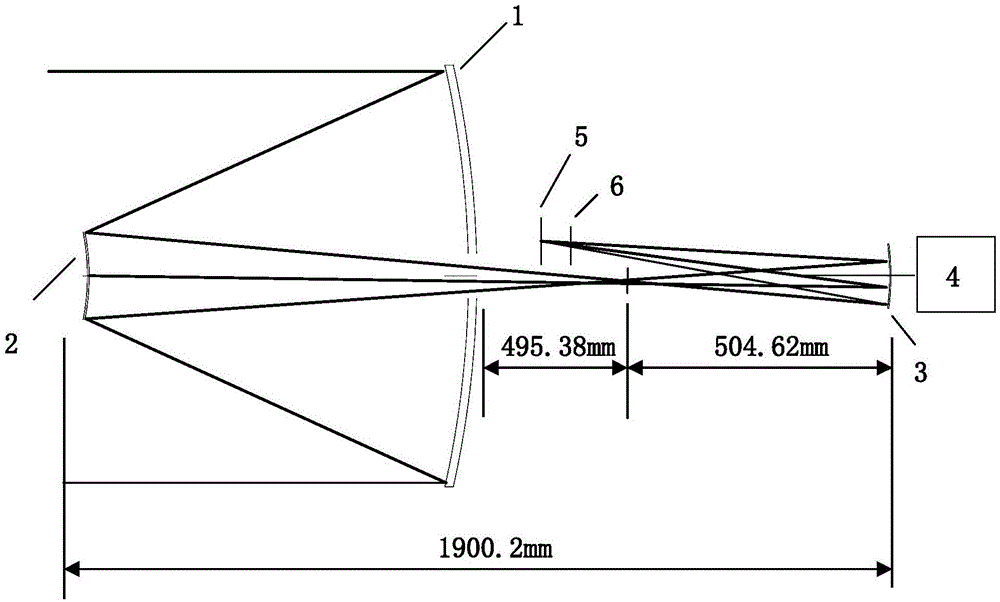
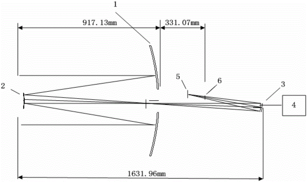
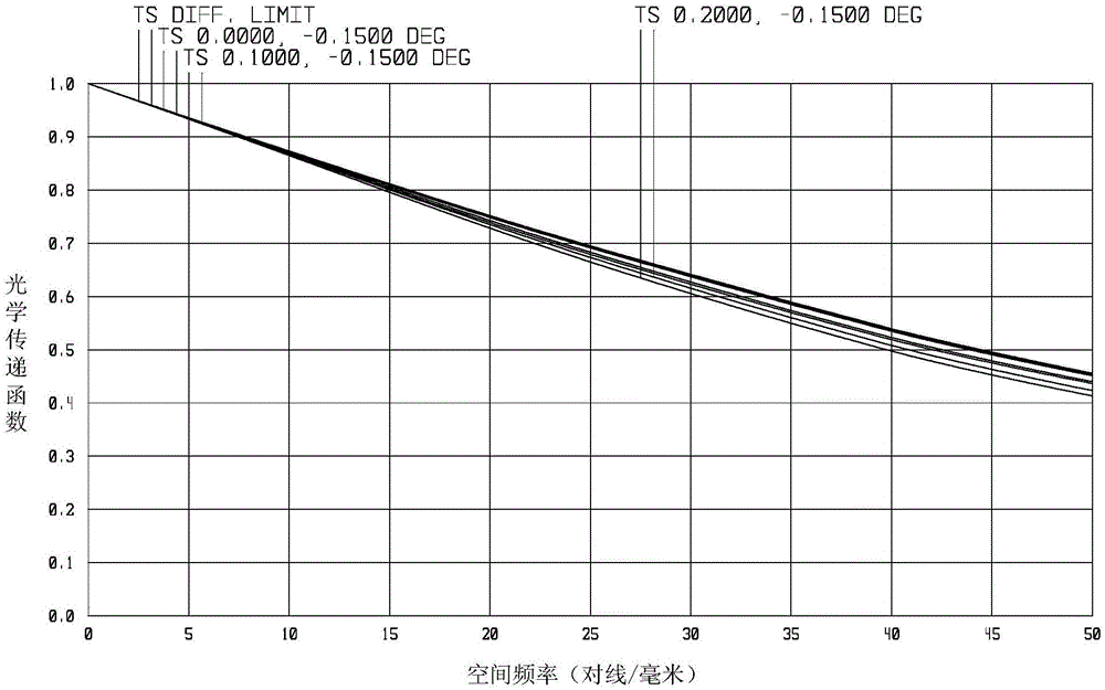
[0018] The working spectrum of the embodiment of the present invention is 0.45-0.8 μm, the entrance pupil diameter is 1000mm in the long focal length mode, the focal length of the optical system is 12m, the full field of view is 0.4°, and the total system length is 1900.02mm. In the short focal length mode, the entrance pupil diameter is 500mm, the focal length of the optical system is 4m, the full field of view is 3°, and the total length of the system is 1631.96mm. In the telephoto mode, the implementation scheme is as follows figure 1 As shown, the optical system of the present invention includes: a primary mirror 1 , a secondary mirror 2 , a third mirror 3 , a drive motor 4 , a focal plane detector 5 and a variable aperture diaphragm 6 . The primary mirror 1, the secondary mirror 2, the third mirror 3 and the variable aperture diaphragm 6 are coaxial, the primary mirror 1 and the secondary mirror 2 form a classic R-C system, and form a real image, which passes through the ...


PUM


Abstract

A coaxial triple-mirror zoom optical system based on photo-isomeric materials, which consists of a primary mirror, a secondary mirror, three mirrors, and a variable aperture diaphragm located at the exit pupil of the system in short-focus mode. The aperture diaphragm of the system is located on the primary mirror. The primary mirror and the secondary mirror constitute a set of classic R-C optical system. The radiation beam of the target scene is converged by the primary and secondary mirrors to form an intermediate real image, which is imaged by the three mirrors to the focal plane of the optical system. The primary mirror, secondary mirror, and three mirrors of this optical system are all made of photoisomerized materials. During the zooming process of the optical system, its material properties are used to control the change of the aspheric coefficient of the mirror. Finally, the radius of curvature of all mirrors in the system remains unchanged In this case, the system has the characteristics of long focal length, high resolution, short focal length and large field of view at the same time only through the change of the aspheric coefficient of the mirror and a small amount of adjustment of the mirror spacing.

Description

technical field [0001] The invention belongs to the technical field of spaceflight optical remote sensors, and relates to a coaxial three-reversal zoom optical system based on photoisomerization materials. Background technique [0002] With the continuous development of space optical remote sensing technology, the functional requirements for reconnaissance cameras are becoming increasingly strict. Especially in the field of environmental disaster reduction and military reconnaissance, it is hoped that the camera can complete the general survey of large-scale ground objects and targets, and at the same time it needs to be able to conduct detailed surveys of specific areas. The census emphasizes the wide coverage capability of the camera, and mainly conducts large-scale medium and low-resolution imaging to complete the observation and search of global targets; the detailed investigation emphasizes the ability of the camera to obtain detailed information, mainly for important a...

Claims


Application Information

Patent Timeline
Patent Type & Authority Patents(China)
IPC IPC(8): G02B27/00G02B7/182G02B17/06G02B5/10G01C11/02
Inventor 苏云张鹏斌胡斌汤天瑾
Owner BEIJING RES INST OF SPATIAL MECHANICAL & ELECTRICAL TECH
Learn More