
A two-phase hydrogenation reactor and a two-phase hydrogenation method

A reactor and additive technology, applied in hydrotreating process, through aromatics hydrorefining, hydrocarbon oil cracking and other directions, can solve the problem of small reactor, achieve the effect of small size, large-scale, small size

Active Publication Date: 2014-05-14
CHINA PETROLEUM & CHEM CORP +1
View PDF10 Cites 4 Cited by
  • Summary
  • Abstract
  • Description
  • Claims
  • Application Information

AI Technical Summary

Problems solved by technology

The reactors of this method are generally small, and hydrogen dissolving equipment needs to be set up between the reactors, and a large amount of circulating oil is required to carry hydrogen

Method used


Image

  • A two-phase hydrogenation reactor and a two-phase hydrogenation method

Examples


Embodiment 1

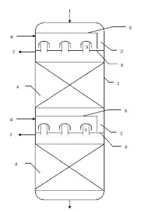
[0028] The reactor adopts such as figure 1 The structure shown. The two-phase hydrogenation reactor adopts two catalyst beds. A hydrogen dissolving device is installed between the reactor inlet and the catalyst bed. The downcomer channel is arranged on the side close to the reactor wall. The total flow cross-sectional area of ​​the downcomer channel is the reactor inlet. The flow cross-sectional area of ​​the feed pipe is 1.0 times, and the flow cross-sectional area between the bottom edge of the downcomer channel and the gas-liquid distribution plate is 1.2 times the flow cross-sectional area of ​​the reactor feed pipe. The gas-liquid distribution plate is provided with a suction type gas-liquid distributor with a bubble cap structure, and the height of the bubble cap bottom of the gas-liquid distributor from the gas-liquid distribution plate surface is 2.0 times the height of the bottom edge of the downcomer channel from the gas-liquid distribution plate surface.

[0029] See T...


PUM

PropertyMeasurementUnit
densityaaaaaaaaaa
diameteraaaaaaaaaa
specific surface areaaaaaaaaaaa

Abstract

The invention provides a two-phase hydrogenation reactor and a two-phase hydrogenation method. Each space surrounded by the upper parts of each gas-liquid distributor, a corresponding liquid-phase collecting tray and a corresponding downcomer is a gas-phase chamber. Hydrogen is introduced into the gas-phase chambers from outside of the reactor. The liquid phase in the upper part of the reactor is collected by the liquid-phase collecting trays and flows onto gas-liquid distributing trays through the downcomers. The gas phase and the liquid phase are subjected to violent mass transfer by the gas-liquid distributors so that the hydrogen can be dissolved in the liquid phase well. The gas phase and the liquid phase in gas and liquid materials are separated after passing through the gas-liquid distributing trays. The liquid phase where the hydrogen is dissolved goes downward into catalyst bed layers to perform hydrogenation. The gas phase converges under the gas-liquid distributors and is discharged from the reactor. The two-phase hydrogenation reactor and the two-phase hydrogenation method can further enhance reaction effects of two-phase hydrogenation.

Description

Technical field [0001] The invention relates to a two-phase hydrogenation reactor and a two-phase hydrogenation method, in particular to a two-phase hydrogenation reactor and a two-phase hydrogenation method for producing high-quality diesel products by the two-phase hydrogenation of diesel raw materials, and belongs to petroleum Chemical industry. Background technique [0002] As people's awareness of environmental protection continues to increase, environmental laws and regulations have stricter requirements on engine exhaust emissions, and various fuel standards require S and N content to become more stringent. At the same time, due to the continuous increase of crude oil extraction and the continuous reduction of conventional crude oil reserves, the trend of crude oil deterioration is becoming more and more serious. The S and N of middle distillates obtained by direct distillation of crude oil and middle distillates obtained by secondary processing such as coking and catalyti...

Claims


Application Information

Patent Timeline
Patent Type & Authority Applications(China)
IPC IPC(8): C10G45/02C10G45/44C10G47/00C10G65/00
Inventor 王喜彬郭蓉曾榕辉蒋立敬
Owner CHINA PETROLEUM & CHEM CORP
Learn More