Combined type ceiling radiant plate

A composite, radiant panel technology, applied in the field of terminal devices, can solve problems such as affecting the temperature and heat radiation effect, and achieve the effect of enhancing the convective heat transfer effect, easy installation and use, and good thermal conductivity.

Inactive Publication Date: 2014-05-14
CHINA ACAD OF BUILDING RES
View PDF5 Cites 4 Cited by
  • Summary
  • Abstract
  • Description
  • Claims
  • Application Information

AI Technical Summary

Problems solved by technology

However, in the dry method currently used, the radiant panel and the suspended ceiling are not assembled together, which affects the thermal radiation effect of the temperature

Method used


Image

  • Combined type ceiling radiant plate
  • Combined type ceiling radiant plate
  • Combined type ceiling radiant plate

Examples


Embodiment Construction

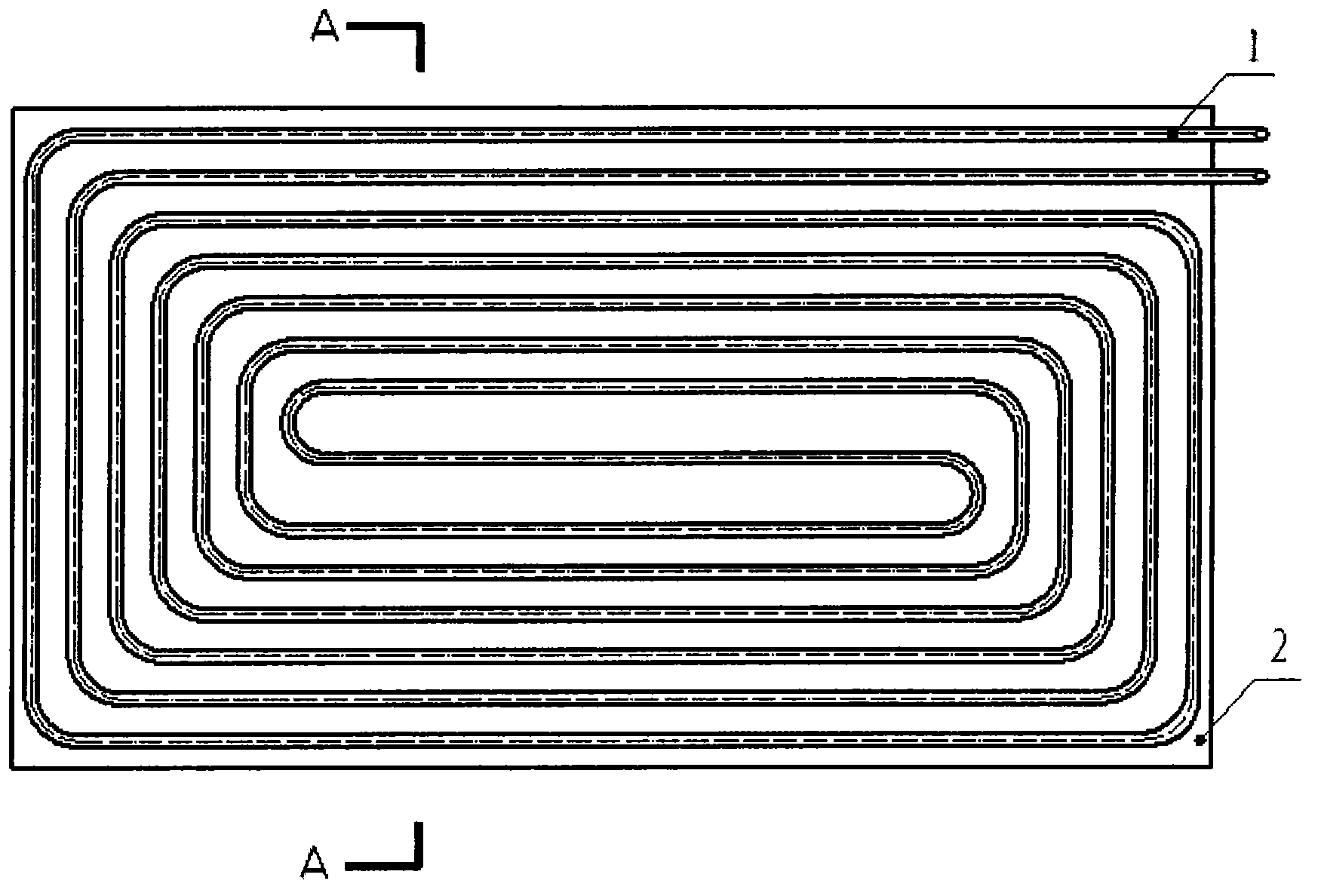
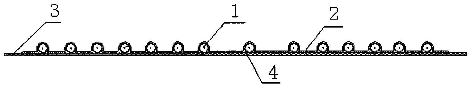
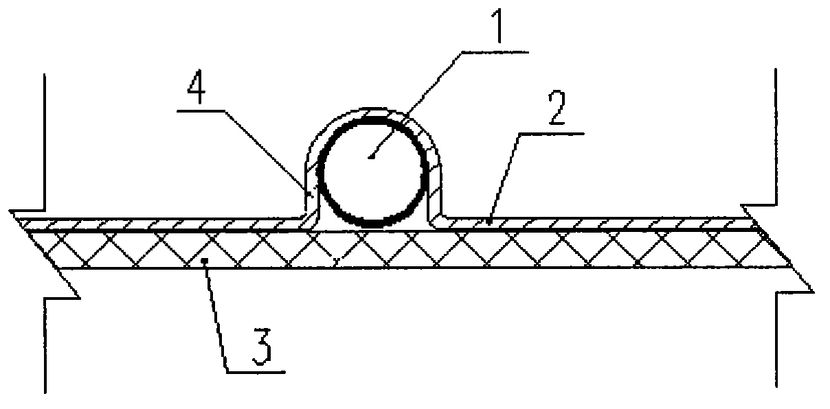
[0021] figure 1 and figure 2 Respectively shown are the bottom view and the section view of the composite ceiling radiant panel, in which the decorative ceiling panel 3 is in figure 1 not shown in . As shown in the figure, the composite suspended ceiling radiant panel of the present invention is composed of a radiant coil 1 , a heat conduction plate 2 and a decorative suspended ceiling panel 3 . The radiant coil 1 is a twisted plastic pipe or metal pipe with a water inlet and a water outlet, and the radiant coil 1 is loaded with high / low temperature flow medium. The heat conduction plate 2 is prefabricated with a pipe groove 4 integral with it. Such as image 3 As shown, the pipe groove 4 is an inverted U shape, and protrudes above the heat conducting plate 2 . The pipe groove 4 is processed according to the actual planned laying path of the radiant coil 1 , and its direction is consistent with that of the radiant coil 1 . The internal size of the pipe groove 4 matches ...


PUM


Abstract

The invention relates to a combined type ceiling radiant plate, belongs to terminal devices of independent temperature and humidity control central air conditioners and can be used in an air conditioning system for refrigeration and heating. A radiant ceiling is composed of a radiant coiler, a heat conduction plate good in heat conduction performance, a decoration ceiling panel and the like. The inflection type radiant coiler is clamped in a pipe groove of the heat conduction plate to increase the downward radiant quantity of the radiant ceiling. The heat conduction plate can be machined into different specifications according to the onsite building structure condition. The decoration panel with or without micro holes clings to the lower surface of the heat conduction plate to serve as a ceiling face, convection heat exchange of the radiant plate and indoor air is improved while radiant heat exchange is conducted, and the refrigeration/heating capability is improved.

Description

technical field [0001] The invention belongs to a terminal device of a central air conditioner with independent temperature and humidity control, and can be used for cooling and heating of an air conditioning system. Background technique [0002] Building energy consumption is the main form of energy consumption. Building energy conservation has become a worldwide trend and a basic trend in the development of modern technology. At the same time, it is becoming more and more important and urgent to improve the quality of indoor environment, improve comfort and reduce environmental pollution. [0003] At present, it is generally believed that the temperature and humidity independent control system is an effective way to solve the disadvantages of traditional air conditioners. There are great prospects for development in the future. [0004] The temperature and humidity independent control system adopts two independent systems to control and adjust the indoor temperature and ...

Claims


Application Information

Patent Timeline
Patent Type & Authority Applications(China)
IPC IPC(8): F24F1/00
Inventor 袁东立赵羽黄涛
Owner CHINA ACAD OF BUILDING RES
Why Eureka
Try Eureka