Switching control method and control circuit and switching power supply with control circuit

A switching power supply and switching control technology, applied in the field of electronics, can solve the problems of slow discharge speed and slow turn-off speed.

Active Publication Date: 2014-05-14
SILERGY SEMICON TECH (HANGZHOU) CO LTD
View PDF2 Cites 3 Cited by
  • Summary
  • Abstract
  • Description
  • Claims
  • Application Information

AI Technical Summary

Problems solved by technology

[0009] With the existing technology, since the base of the transistor Q3 accumulates more charges when the transistor Q3 is in the on state, its discharge speed is slower, resulting in a slower turn-off speed

Method used


Image

  • Switching control method and control circuit and switching power supply with control circuit
  • Switching control method and control circuit and switching power supply with control circuit
  • Switching control method and control circuit and switching power supply with control circuit

Examples


Embodiment 1

[0065] figure 2 It is a schematic flowchart of a switching control method suitable for switching power supplies provided in this embodiment. see figure 2 As shown, it mainly includes the following steps:

[0066] Step 201: Generate a driving current signal according to the sampled voltage signal.

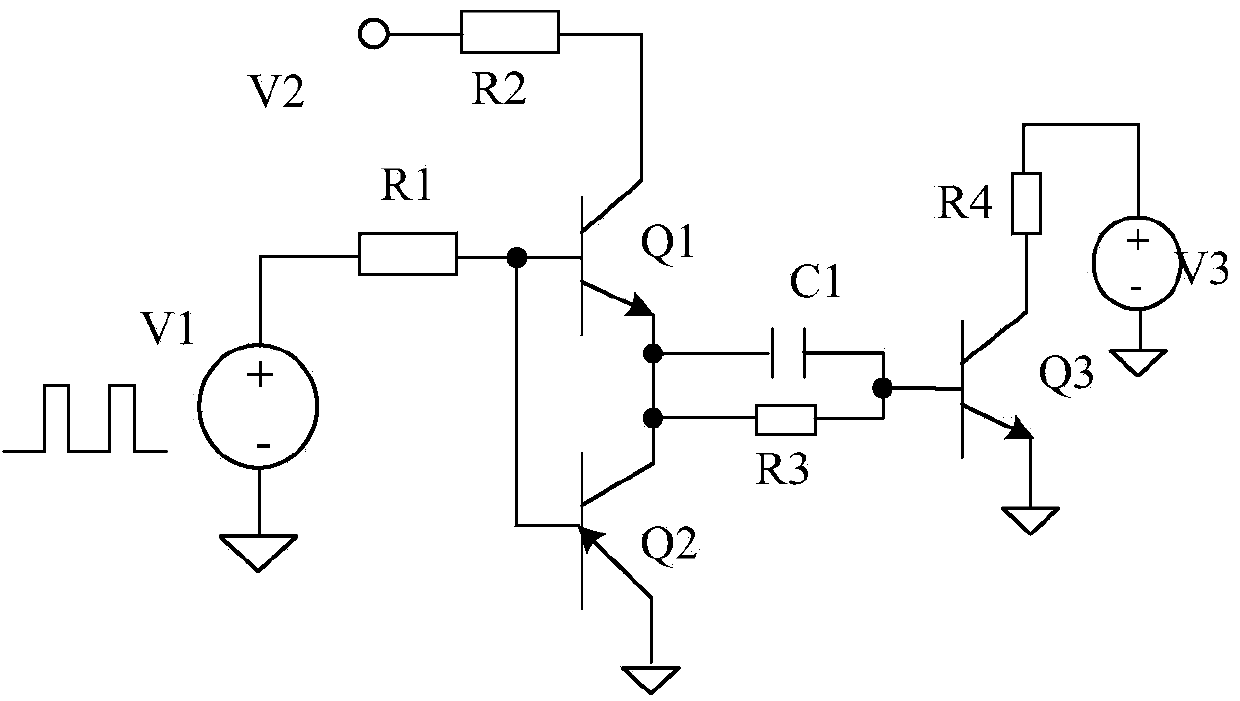
[0067] In this embodiment, the transistor Q1 is used as the power switch of the switching power supply, and the collector of the transistor Q1 is connected to the inductive element (such as the inductor L) in the switching power supply, so the collector current Ic flowing through the transistor Q1 is equal to the inductance in the switching power supply Current IL. The specific connection relationship can be, but not limited to, see Figure 10 shown.

[0068] As an illustration of this embodiment, the emitter voltage of the transistor Q1 can be sampled on the emitter of the transistor Q1 as the sampling voltage signal Vcs of this embodiment. For details, see Figure 6-8 show...

Embodiment 2

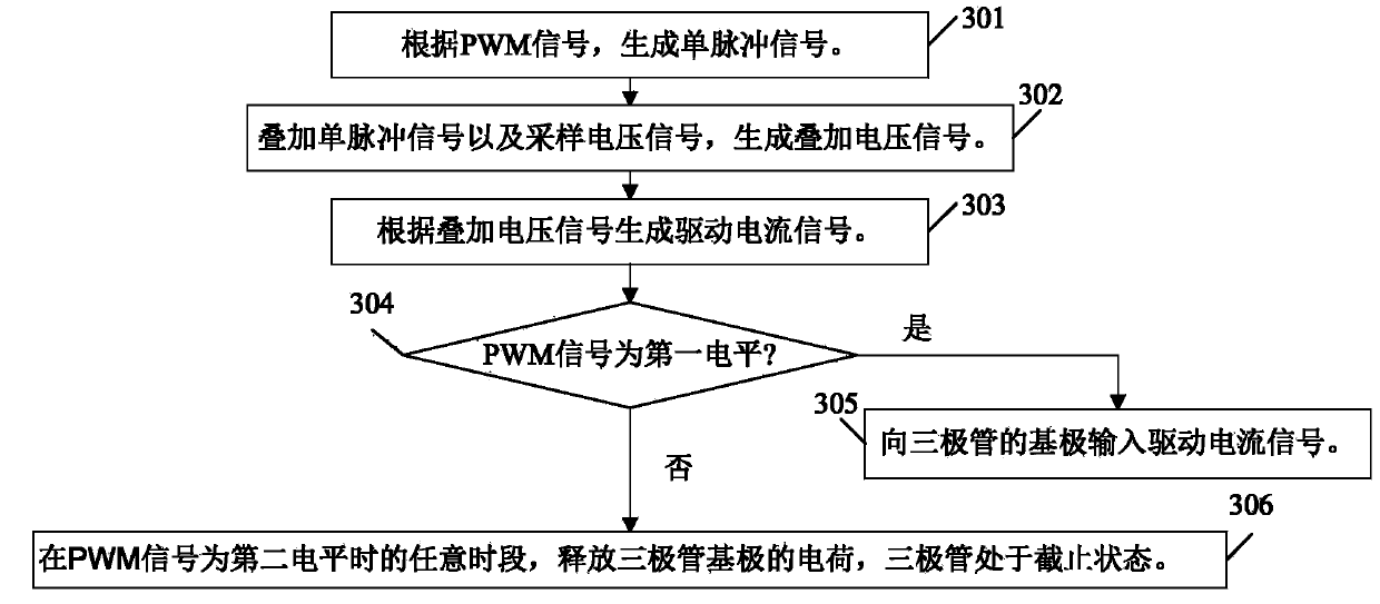
[0080] image 3 For the flow diagram of a switching control method suitable for switching power supplies provided in Embodiment 2, see image 3 As shown, the process of this embodiment mainly includes the following steps:

[0081] Step 301: Generate a single pulse signal according to the PWM signal.

[0082] As an illustration of this embodiment, specifically, a single pulse signal (denoted as Vm) may be generated according to the trigger of the first transition edge of the PWM signal, and the period of the single pulse signal Vm is consistent with the period of the PWM signal.

[0083] Wherein, the first transition edge of the PWM signal is: a transition edge transitioning from the second level to the first level.

[0084] for example Figure 9 As shown, when the second level is low and the first level is high, the first transition edge is the rising edge of the PWM signal.

[0085] When the second level is high level and the first level is low level, the first transition...

Embodiment 3

[0101] Figure 4 It is a schematic flowchart of a switching control method suitable for switching power supplies provided in this embodiment. see Figure 4 As shown, the difference between this embodiment and embodiment 2 mainly lies in:

[0102] Also further include before step 306:

[0103] Step 401: Sampling and acquiring the peak voltage of the sampling voltage signal.

[0104] When the PWM signal is at the first level, the emitter current Ie of the transistor Q1 is the superposition of the base current Ib of the transistor Q1 and the collector current Ic of the transistor Q1. The signal Vcs contains not only the information of the collector current Ic, but also the information of the base current Ib, which cannot accurately represent the information of the collector current Ic, that is, the information of the inductor current IL of the switching power supply.

[0105] And when the PWM signal is at the second level, the drive current signal Ib input to the base of the ...


PUM


Abstract

The invention relates to the field of electronics, and discloses a switching control method and control circuit and a switching power supply with the control circuit. The method comprises the steps that a driving current signal is generated according to a sampling voltage signal, the waveform of the driving current signal is made to follow the waveform of the sampling voltage signal, the sampling voltage signal comprises collector current information of a triode as a switching power supply power switch, and when a pulse width modulating signal is at a first level, the driving current signal is input into the base electrode of the triode, and the triode is in a saturation conduction state; when the pulse width modulation signal is at any preset time frame of a second level, the electric charge of the base electrode of the triode is released, and the triode is in a cut-off state. According to the technical scheme, the switching speed of the triode can be improved conveniently.

Description

technical field [0001] The invention relates to the field of electronics, in particular to a switch control method, a control circuit and a switch power supply with the control circuit. Background technique [0002] The switching power supply is a power supply that controls the on-off time ratio of the power switch tube through the pulse width modulation (PulseWidthModulation, PWM) signal to maintain a stable output voltage. [0003] Due to the advantage of its saturation voltage drop, the triode is widely used in switching power supply circuits as the power switch tube of switching power supply. [0004] figure 1 For the schematic diagram of the circuit principle of using the triode Q3 as the power switching tube in the switching power supply of the prior art, see figure 1 Shown: [0005] When the PWM signal V1 is at a high level, the switch Q2 is turned off, the switch Q1 is turned on, and the drive current is input to the base of the transistor Q3, and the transistor Q...

Claims


Application Information

Patent Timeline
Patent Type & Authority Applications(China)
IPC IPC(8): H02M3/335
CPCH02M3/33523H03K17/04213H02M3/33507
Inventor 陈惠强韩云龙徐孝如陈伟
Owner SILERGY SEMICON TECH (HANGZHOU) CO LTD
Why Eureka
Try Eureka