
Power device soft switching-off circuit

A technology of power devices and circuits, which is applied in the field of soft-off circuits, can solve problems such as temperature rise of power devices, affecting the performance and safety of power devices, and increasing losses in the turn-off process, so as to reduce induced voltage, reduce losses and Effect of heat generation and loss reduction

Active Publication Date: 2018-03-06
河南嘉晨智能控制股份有限公司
View PDF11 Cites 7 Cited by
  • Summary
  • Abstract
  • Description
  • Claims
  • Application Information

AI Technical Summary

Problems solved by technology

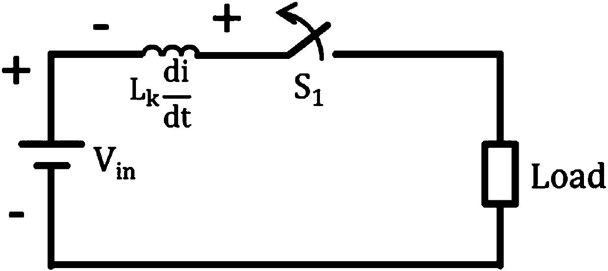
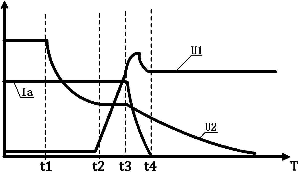
[0004] like figure 2 As shown, by subdividing the turn-off of power devices, it can be divided into three stages: t1~t2, t2~t3, t3~t4. The existing technology will extend the three stages at the same time, resulting in an increase in the loss of the entire turn-off process. , the temperature of the power device rises, which affects the performance and safety of the power device

Method used


Image

  • Power device soft switching-off circuit
  • Power device soft switching-off circuit
  • Power device soft switching-off circuit

Examples


Embodiment 1

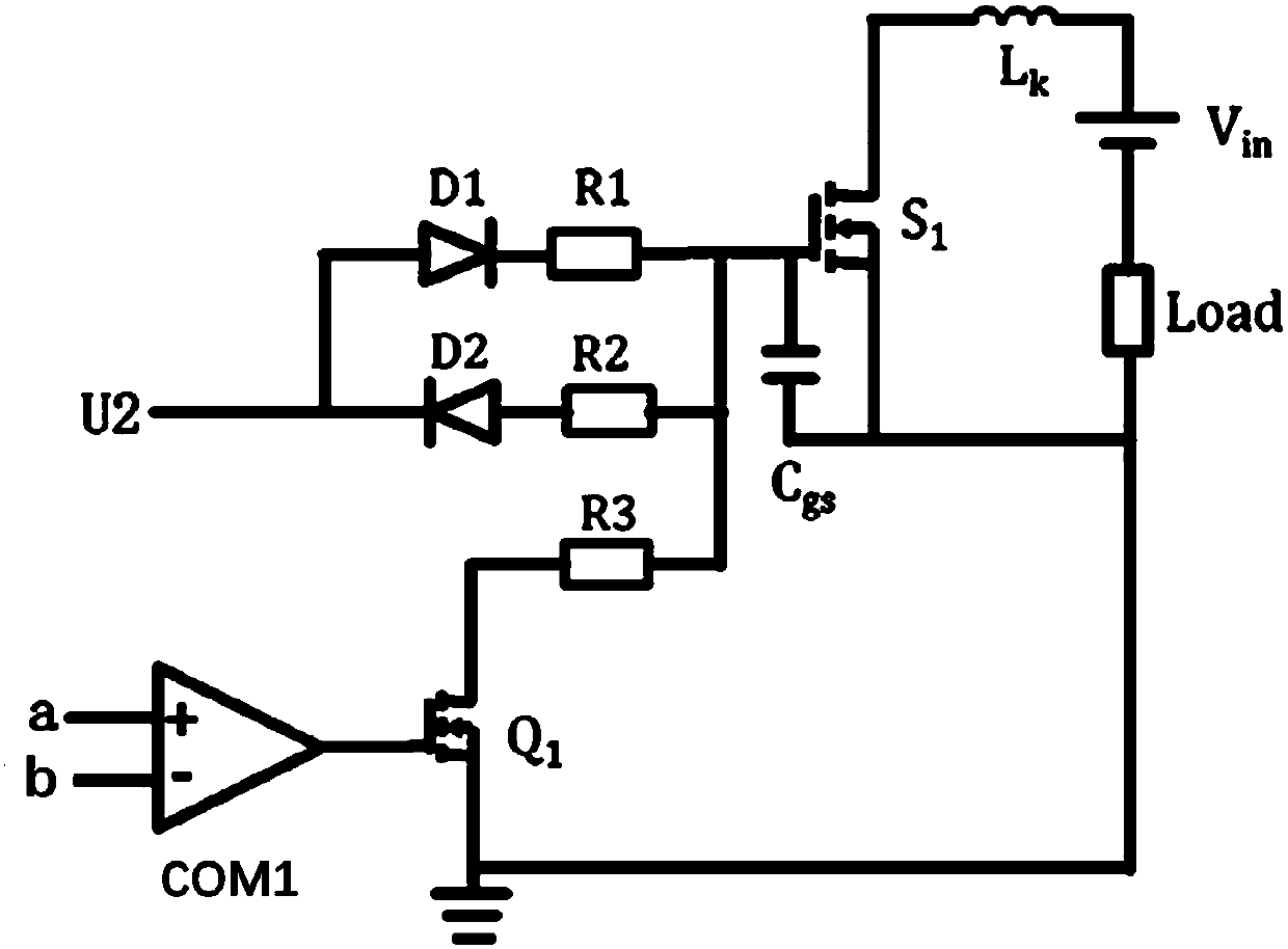
[0031] Such as image 3 , Figure 4 As shown, the circuit description: Vin is the circuit input voltage, Lk is the line inductance, S1 is the power device, Cgs is the gate capacitance of the power device, the gate capacitance voltage determines the turn-on and turn-off of the power device, the first diode D1 and the second resistor R1 are the drive circuit when the power device is turned on, the second diode D2 and the second resistor R2 are the drive circuit when the power device is turned off, the third resistor R3 is the parallel resistance when the power device is turned off, and the first The control switch Q1 is a switch for controlling resistors connected in parallel.

[0032] Stage t1~t2: Since the reference voltage a>sampling voltage b, the first control switch Q1 is in the on state, at this time the second resistor R2 and the third resistor R3 are in a parallel state, and since the value of the third resistor R3 is small, the second The parallel connection of the r...

Embodiment 2

[0036] Such as Figure 5 , Figure 6 As shown, on the basis of the embodiment, the second control switch Q2, the first voltage regulator transistor Z1 and the second voltage regulator transistor Z2 are added.

[0037] Stage t1~t2: power device withstand voltage U1<nominal voltage of the first voltage regulator tube Z1, the second control switch Q2 is not turned on, the first control switch Q1 is turned on under the action of Vcc, the second resistor R2 and the third resistor R3 realize in parallel.

[0038] Stage t2~t3: The voltage of the power device S1 starts to rise, but there is still a power device withstanding voltage U1<the nominal voltage of the first voltage regulator tube Z1, the second control switch Q2 is not turned on, the first control switch Q1 remains on, and the second control switch Q1 remains on. The resistor R2 is connected in parallel with the third resistor R3.

[0039] Stage t3~t4: at time t3, the withstand voltage of the power device U1>the nominal v...


PUM


Abstract

The invention discloses a power device soft switching-off circuit comprising a load electronic component Load, an input voltage and a lead inductor arranged in the same series circuit of a power device. The power device is connected to power device withstand voltage, driving voltage and the gate capacitor of the power device. A driving circuit is disposed on a circuit where the power device is connected with the driving voltage in series. The power device soft switching-off circuit processes a switching-off process in segments. The switching-off speed is increased at the phase t1-t2 and the phase t2-t3, and is slowed down at the phase t3-t4. The switching-off speed is increased at the phase t2-t3 in order to reduce the loss of the switching-off phase, and is slowed down at the phase t3-t4in order to reduce the induced voltage caused by switching-off. The total switching-off time and total switching-off loss are balanced in order to reduce the voltage applied to the power device and reduces the losses and heat generation of the power device.

Description

technical field [0001] The invention relates to the field of electrical circuits, in particular to a soft-off circuit of a power device. Background technique [0002] With the rapid development of society, especially the continuous advancement of technology and the popularization of electricity, people's lives are inseparable from electricity. The popularization of electricity designs people's clothing, food, housing, transportation, life and work; with the continuous expansion of generator sets, various large-scale machinery powered by electricity is gradually increasing. Among many electrical machinery and circuits, power devices are a kind of Very common large power device. [0003] Power devices are connected in the circuit through leads, and there is an inductance Lk in the leads; when the power device is turned off, the current will change suddenly, and the sudden change of current will induce an induced voltage on the lead inductance Lk induced voltage Will be su...

Claims


Application Information

Patent Timeline
Patent Type & Authority Applications(China)
IPC IPC(8): H02M1/08
Inventor 武凯李飞
Owner 河南嘉晨智能控制股份有限公司
Learn More