Method for machining gas compressor fixed blade ring of gas turbine

A technology for gas turbines and processing methods, which is applied in the field of processing gas turbine compressor vane rings, can solve problems such as multiple tool changes, poor processing accuracy, and large deformation of cutting workpieces, and meet assembly requirements, good processing stability, and compression The effect of tightness weakening

Active Publication Date: 2014-05-21
SHANGHAI ELECTRIC POWER GENERATION EQUIPMENT CO LTD
View PDF3 Cites 21 Cited by
  • Summary
  • Abstract
  • Description
  • Claims
  • Application Information

AI Technical Summary

Problems solved by technology

There are many disadvantages in this processing method: the cost of using four tools is high (the tool loss is particularly large due to powerful cutting, arc cutting, and root cutting), high equipment cost (NC gantry milling must be used), and many processing procedures ( The tool needs to be changed several times during the machining process), the machining is complex (different blade root type inclined slots need to be equipped with different tools), the processing time is long (4 knives are required to complete each slot processing in sequence), and the machining and cutting workpiece has large deformation ( Large thermal deformation during cutting, large workpiece deformation during clamping), poor machining accuracy, and poor machining quality

Method used


Image

  • Method for machining gas compressor fixed blade ring of gas turbine
  • Method for machining gas compressor fixed blade ring of gas turbine
  • Method for machining gas compressor fixed blade ring of gas turbine

Examples


Embodiment Construction

[0032] The implementation of the present invention will be illustrated by specific specific examples below, and those skilled in the art can easily understand other advantages and effects of the present invention from the contents disclosed in this specification.

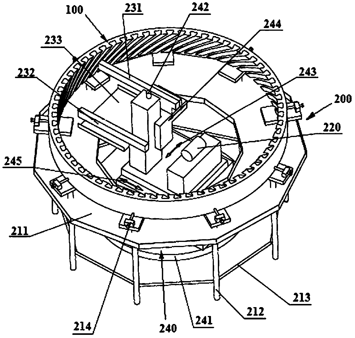
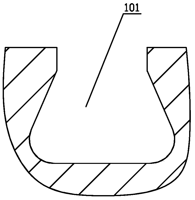
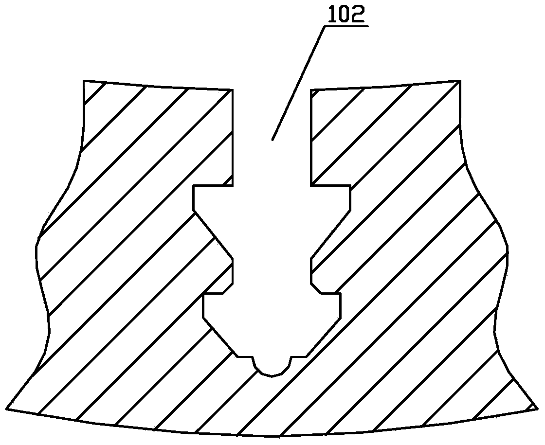
[0033] see Figure 1 to Figure 4 . It should be noted that the structures, proportions, sizes, etc. shown in the drawings attached to this specification are only used to match the content disclosed in the specification, for those who are familiar with this technology to understand and read, and are not used to limit the implementation of the present invention. Limiting conditions, so there is no technical substantive meaning, any modification of structure, change of proportional relationship or adjustment of size, without affecting the effect and purpose of the present invention, should still fall within the scope of the present invention. within the scope covered by the disclosed technical content. At the same tim...


PUM


Abstract

The invention provides a method for machining a gas compressor fixed blade ring of a gas turbine. The method comprises the steps that a fixed blade ring blank is placed on a permanent magnetic chuck workbench of a machine tool, and clamped by the permanent magnetic chuck workbench, and the outer circumferential surface, the annular inner conical surface and the upper end face of the fixed blade ring are turned at a time; the bottom plane is machined; the turned fixed blade ring blank is placed on a working platform of a five-axis numerical control wire cutting machine, the cutting inclination of the five-axis numerical control wire cutting machine ranges from 0 degree to 60 degrees, and is adjustable, and the axis of the fixed blade ring blank coincides with the axis of a rotary platform of the five-axis numerical control wire cutting machine; the cut portion of a wire electrode of the five-axis numerical control wire cutting machine is made to be opposite to a molded line inclined groove in the annular inner conical surface in position by adjusting the rotary platform on a machine tool body, the inclination angle of the cut portion of the wire electrode is equal to the inclination angle of the molded line inclined groove, and the molded line inclined groove is machined; the rotary platform on the machine tool body is adjusted repeatedly, and machining of all the molded line inclined grooves is accomplished. According to the method for machining the gas compressor fixed blade ring of the gas turbine, the machining cost is low, the machining speed is high, the degree of thermal deformation is low, machining stability is good, and machining precision is high.

Description

technical field [0001] The invention relates to the technical field of processing technology for a gas turbine compressor stator ring, in particular to a processing method for a gas turbine compressor stator ring. Background technique [0002] The gas turbine compressor vane ring is one of the core components of the gas turbine. The quality of the compressor vane ring directly affects the compression ratio of the gas turbine compressor, which in turn affects the combustion quality and power generation efficiency of the gas turbine. Therefore, it is important to ensure the compressor vane ring The processing quality is very important. [0003] Due to the particularity of the structure of the stator vane ring of the gas turbine compressor, it is necessary to process the unequal parting line chute on the annular inner cone surface, such as Figure 1 to Figure 4 As shown, the structural characteristics of the unequal parting line chute of the annular inner cone surface of the co...

Claims


Application Information

Patent Timeline
Patent Type & Authority Applications(China)
IPC IPC(8): B23P15/00
CPCB23P15/02
Inventor 蔡振铭
Owner SHANGHAI ELECTRIC POWER GENERATION EQUIPMENT CO LTD
Why Eureka
Try Eureka