Energy recycling equipment of aeration water flow

An aeration device and energy technology, applied in the field of aeration systems, can solve the problems of whether the flow energy of aeration water can be used, and achieve the effects of simple structure, increased flow energy of water, and easy realization.

Active Publication Date: 2014-05-21
兴港红环保设备河北有限公司
View PDF7 Cites 3 Cited by
  • Summary
  • Abstract
  • Description
  • Claims
  • Application Information

AI Technical Summary

Problems solved by technology

[0004] The technical problem to be solved by the present invention is the problem that the water flow energy generated by aeration cannot be utilized, and an energy recycling device for aeration water flow is provided to convert the water flow energy generated by aeration into reusable energy

Method used


Image

  • Energy recycling equipment of aeration water flow
  • Energy recycling equipment of aeration water flow
  • Energy recycling equipment of aeration water flow

Examples


Embodiment 1

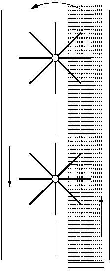
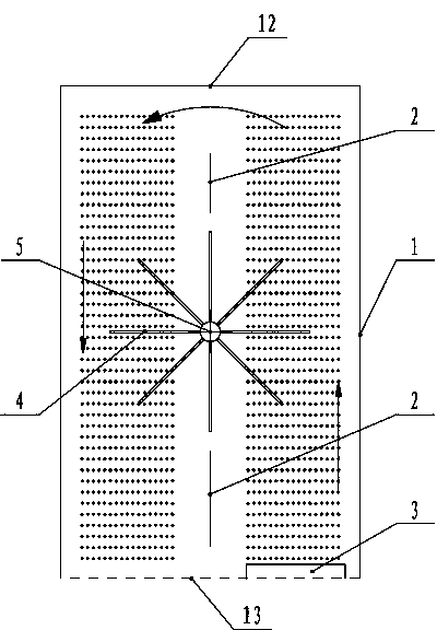
[0044] Such as figure 1 As shown, it includes a cylinder 1, and a vertical partition 2 is arranged inside the cylinder 1. The vertical partition 2 divides the cylinder 1 into left and right parts, and the aeration device 3 of the aeration system is arranged on its right side The bottom of the cylinder 1-1; the right cylinder 1-1 and the left cylinder 1-2 of the cylinder 1 are respectively provided with paddles 4 that can be impacted by the aeration water flow, and the paddles 4 drive the output shaft to rotate output energy. The output shaft is a horizontal output shaft 5 arranged at the front and back direction of the separator 2 , and the paddle 4 is fixedly arranged on the circumference of the horizontal output shaft 5 . A vertical partition 2 is arranged in the cylinder body 1, and an aeration device 3 is arranged at the lower part of the right cylinder body 1-1, so that the direction of the water flow in the cylinder body on both sides is different; The impact of the wa...

Embodiment 2

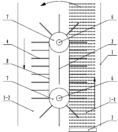
[0049] Such as Figure 4 , Figure 5 As shown, it includes a cylinder 1, and a vertical partition 2 is arranged inside the cylinder 1. The vertical partition 2 divides the cylinder 1 into left and right parts, and the aeration device 3 of the aeration system is arranged on its right side The bottom of the cylinder 1-1; the right cylinder 1-1 and the left cylinder 1-2 of the cylinder 1 are respectively provided with paddles 4 that can be impacted by the aeration water flow, and the paddles 4 drive the output shaft to rotate output energy. The upper and lower parts of the partition 2 are respectively provided with horizontal shafts 6 in the front and rear directions, and wheel bodies 7 are respectively arranged on the upper and lower horizontal shafts 6, and the wheel bodies 7 on the upper and lower horizontal shafts 6 are linked by a linkage body 8 A paddle 4 is arranged on the linkage body 8; at least one of the upper and lower horizontal shafts 6 can be linked with the whee...

Embodiment 3

[0053] Such as Figure 6 As shown, the difference between the third embodiment and the second embodiment is that two vertical partitions 2 are arranged side by side in the cylinder 1, and the two vertical partitions 2 divide the cylinder 1 into three parts: left, middle and right. The aeration device 3 of the aeration system is arranged at the bottom of the intermediate cylinder body 1-3; at the same time, two sets of wheel bodies 7 and linkage bodies 8 are arranged side by side in the cylinder body 1. The direction of rotation of its water flow and paddle 4 is shown by the arrow in the figure. This embodiment is suitable for occasions where the cylinder body 1 is relatively large and the aeration device 3 is relatively small.


PUM


Abstract

The invention discloses energy recycling equipment of aeration water flow. The energy recycling equipment comprises a barrel, wherein a vertical partition plate is arranged inside the barrel; the barrel is divided into a left part and a right part by the vertical partition plate; an aerating apparatus of an aerating system is arranged at the bottom of the right barrel; paddles capable of being impacted by aeration water flow are respectively arranged inside the left barrel and the right barrel of the barrel, and drive an output shaft to rotate and output energy; the vertical partition plate is arranged inside the barrel; the aerating apparatus is arranged at the lower part of the right barrel, so that the flow inside the two barrels is different in direction; the paddles are impacted by the water flow in different directions inside the two barrels, so that the energy recycling equipment can rotate along the same peripheral direction, and drives the output shaft to rotate. Thus, kinetic energy of the water flow generated by aeration is converted into reusable energy.

Description

technical field [0001] The invention relates to an aeration system, in particular to an energy reuse device for aeration water flow. Background technique [0002] In the sewage treatment industry, the aeration system plays the role of increasing oxygen for the sewage tank. Usually, the aeration device is installed at the bottom or the middle of the sewage tank. Aeration produces a large number of tiny bubbles, which gushes out from bottom to top, and the bubbles will also push The pool water surges upwards and then flows back to the bottom of the pool around the aeration area, forming a circulating water flow. The pool water is pushed up by the aeration bubbles and flows back to the bottom of the pool, which will generate considerable flow energy. Usually, this kinetic energy is not utilized and is wasted. [0003] In the sewage tank of sewage treatment, it is usually equipped with a propulsion system. The propulsion system includes push flow blades connected with power equ...

Claims


Application Information

Patent Timeline
Patent Type & Authority Applications(China)
IPC IPC(8): C02F7/00F03B13/00
CPCY02W10/10
Inventor 张玉
Owner 兴港红环保设备河北有限公司
Why Eureka
Try Eureka