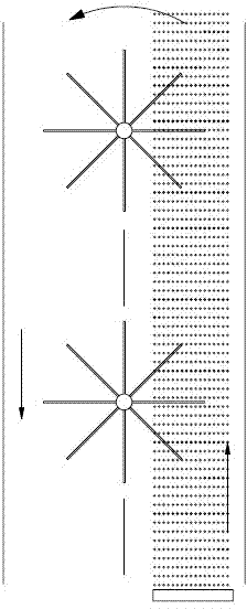
An energy reuse device for aeration water flow
An aeration device and energy technology are applied in the field of aeration systems, which can solve the problems of whether the flow energy of aeration water can be used, and achieve the effects of simple structure, increasing flow energy of water, and improving aeration effect.
- Summary
- Abstract
- Description
- Claims
- Application Information
AI Technical Summary
Problems solved by technology
Method used
Image
Examples
Embodiment 1
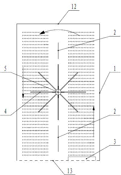
[0044] Such as figure 1 As shown, it includes a cylinder 1, and a vertical partition 2 is arranged inside the cylinder 1. The vertical partition 2 divides the cylinder 1 into left and right parts, and the aeration device 3 of the aeration system is arranged on its right side The bottom of the cylinder 1-1; the right cylinder 1-1 and the left cylinder 1-2 of the cylinder 1 are respectively provided with paddles 4 that can be impacted by the aeration water flow, and the paddles 4 drive the output shaft to rotate output energy. The output shaft is a horizontal output shaft 5 arranged at the front and back direction of the separator 2 , and the paddle 4 is fixedly arranged on the circumference of the horizontal output shaft 5 . A vertical partition 2 is arranged in the cylinder body 1, and an aeration device 3 is arranged at the lower part of the right cylinder body 1-1, so that the direction of the water flow in the cylinder body on both sides is different; The impact of the wa...
Embodiment 2
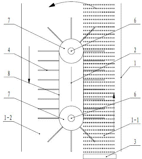
[0049] Such as Figure 4 , Figure 5 As shown, it includes a cylinder 1, and a vertical partition 2 is arranged inside the cylinder 1. The vertical partition 2 divides the cylinder 1 into left and right parts, and the aeration device 3 of the aeration system is arranged on its right side The bottom of the cylinder 1-1; the right cylinder 1-1 and the left cylinder 1-2 of the cylinder 1 are respectively provided with paddles 4 that can be impacted by the aeration water flow, and the paddles 4 drive the output shaft to rotate output energy. The upper and lower parts of the partition 2 are respectively provided with horizontal shafts 6 in the front and rear directions, and wheel bodies 7 are respectively arranged on the upper and lower horizontal shafts 6, and the wheel bodies 7 on the upper and lower horizontal shafts 6 are linked by a linkage body 8 A paddle 4 is arranged on the linkage body 8; at least one of the upper and lower horizontal shafts 6 can be linked with the whee...
Embodiment 3
[0053] Such as Figure 6 As shown, the difference between the third embodiment and the second embodiment is that two vertical partitions 2 are arranged side by side in the cylinder 1, and the two vertical partitions 2 divide the cylinder 1 into three parts: left, middle and right. The aeration device 3 of the aeration system is arranged at the bottom of the intermediate cylinder body 1-3; at the same time, two sets of wheel bodies 7 and linkage bodies 8 are arranged side by side in the cylinder body 1. The direction of rotation of its water flow and paddle 4 is shown by the arrow in the figure. This embodiment is suitable for occasions where the cylinder body 1 is relatively large and the aeration device 3 is relatively small.
PUM
 Abstract
Description
Claims
Application Information
 - R&D
- Intellectual Property
- Life Sciences
- Materials
- Tech Scout
- Unparalleled Data Quality
- Higher Quality Content
- 60% Fewer Hallucinations
Browse by: Latest US Patents, China's latest patents, Technical Efficacy Thesaurus, Application Domain, Technology Topic, Popular Technical Reports.
© 2025 PatSnap. All rights reserved.Legal|Privacy policy|Modern Slavery Act Transparency Statement|Sitemap|About US| Contact US: help@patsnap.com


