
A stepless speed regulating device for CNC machine tool workbench or spindle

A technology of stepless speed regulation and numerical control machine tool, applied in the direction of excitation or armature current control, etc., can solve the problems of limiting the bandwidth of the system frequency band and speed regulation range, the runaway time and dead zone voltage, and restricting the development of the manufacturing industry. Simple structure, high dynamic hardness, good rapidity

Active Publication Date: 2016-08-17
中国科学院沈阳计算技术研究所有限公司
View PDF4 Cites 0 Cited by
  • Summary
  • Abstract
  • Description
  • Claims
  • Application Information

AI Technical Summary

Problems solved by technology

Existing speed control devices for machine tools have complex structures, high power consumption, large pulsating components in the output current provided, intermittent current phenomena, and large runaway time and dead zone voltage, which limits the frequency band of the system Broadband and speed regulation range seriously restrict the development of my country's manufacturing industry

Method used


Image

  • A stepless speed regulating device for CNC machine tool workbench or spindle
  • A stepless speed regulating device for CNC machine tool workbench or spindle
  • A stepless speed regulating device for CNC machine tool workbench or spindle

Examples


Embodiment Construction

[0026] The present invention will be further described in detail below in conjunction with the accompanying drawings and embodiments.

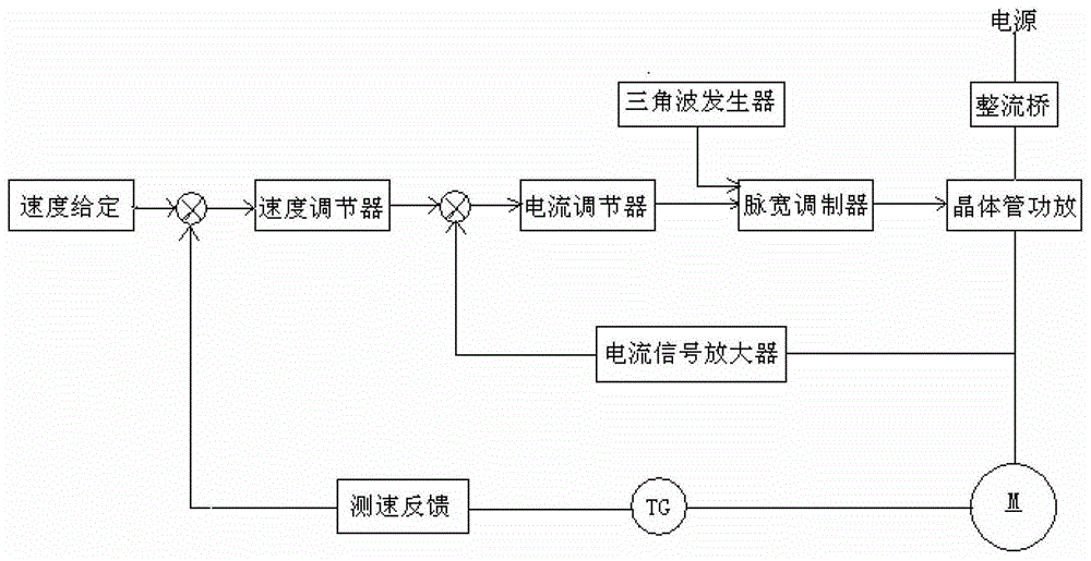
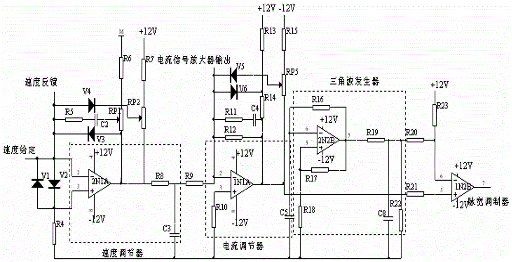
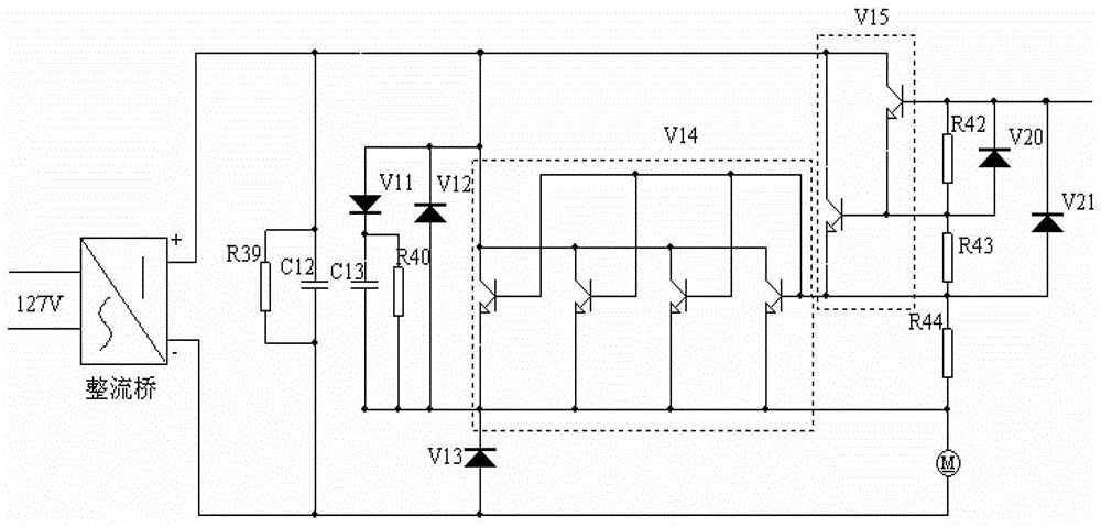
[0027] Such as figure 1 As shown, the structural design of the present invention is realized in this way: the device is a double closed-loop speed regulation system composed of a small current closed loop and a large speed closed loop, which is used to control the speed of the motor. The control loop is composed of a speed regulator, a current regulator, a triangle wave generator, and a pulse width modulator. The main circuit is composed of a rectifier circuit and a transistor power amplifier circuit.

[0028] Its connection is: the power supply unit has a rectification, filter circuit, power supply voltage stabilization circuit, and provides +5V, -5V, +12V, -12V DC power for other functional modules. Both the speed regulator and the current regulator use proportional integral regulators. The two are connected in series. The output of the s...


PUM


Abstract

The invention relates to a stepless speed regulation device for a working table or a spindle of a numerical control machine tool. The device comprises a speed regulator, a current regulator, a triangular wave generator, a pulse width modem, a transistor amplification circuit, a current signal amplifier and a speed measurement feedback circuit. The speed regulator, the current regulator, the pulse width modem and the transistor amplification circuit are connected sequentially. The triangular wave generator is connected with the pulse width modem, the input end of the current signal amplifier is connected with the output end of the transistor amplification circuit, the input end of the current signal amplifier is connected with the input end of the current regulator, and the speed measurement feedback circuit for measuring the rotation speed of a motor is connected with the input end of the speed regulator. The device has the advantages that the bandwidth is wide, and the frequency is high; the transistor 'junction capacitance' is small, and the rapidity is good; the current pulsation is small, and the power factor of a power supply is high; a direct-current power supply of a PWM system is uncontrolled rectification output, the power factor is good, and the dynamic hardness is good.

Description

technical field [0001] The invention belongs to a stepless speed regulating device for the workbench or main shaft of a numerical control machine tool, which is suitable for use in the field of numerical control machine tools, in particular to a circuit for stepless speed regulating of the main shaft of a machine tool. Background technique [0002] Numerical control technology is an important basic industry that reflects the level of the country's comprehensive national strength, and the numerical control rate of machine tools is the core symbol to measure the modernization degree of a country's manufacturing industry. However, the lack of guarantee of CNC machining accuracy has directly and seriously affected the development of my country's manufacturing industry. At present, in order to improve the machining accuracy of the CNC system of machine tools, the production of high-precision and high-level parts plays a vital role in various industries, so designers must improve ...

Claims


Application Information

Patent Timeline
Patent Type & Authority Patents(China)
IPC IPC(8): H02P7/28
Inventor 夏筱筠杨振辉霍淑兰柏松张宏之郭烽
Owner 中国科学院沈阳计算技术研究所有限公司
Learn More