Supercharge Your Innovation With Domain-Expert AI Agents!

Wire bonding apparatus and wire bonding method

一种引线接合、接合点的技术,应用在焊接设备、半导体/固态器件零部件、半导体/固态器件测试/测量等方向,能够解决接合强度降低、损坏装置、污染超声波喇叭等问题,达到防止热渗透、结构简单化的效果

Active Publication Date: 2017-03-01
KAIJOO KK
View PDF4 Cites 0 Cited by
  • Summary
  • Abstract
  • Description
  • Claims
  • Application Information

AI Technical Summary

Problems solved by technology

However, in the second bonding, the oxidation of the surface of the copper lead will reduce the bonding strength
[0012] Also, since the entire substrate (lead frame) is heated on the bonding stage 43, the solder paste and adhesive for bonding the IC chip to the substrate (lead frame), or the chemical substances contained in the substrate, are Be heated and become external gas (Aoutogas) and be volatilized, and pollute ultrasonic horn 33, joint head 31, camera 38 and XY workbench 40, also have the fixing tool etc. of the substrate on the join workbench 43 and surrounding mechanism parts, thereby will impair the function of the device
[0013] Therefore, a bonding member with low heat conduction efficiency, such as a large-scale composite substrate (hiblit substrate) on which a plurality of IC chips are mounted, cannot sufficiently be heated on the electrodes of the IC chip when bonding. In order to improve these problems, Patent Document 1 Disclosed is a wire bonding apparatus that directly heats the bonding surface by irradiating heating light from above the bonding surface

Method used


Image

  • Wire bonding apparatus and wire bonding method
  • Wire bonding apparatus and wire bonding method
  • Wire bonding apparatus and wire bonding method

Examples


Embodiment Construction

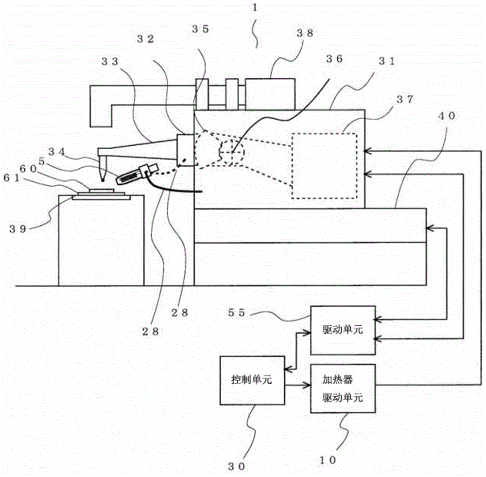
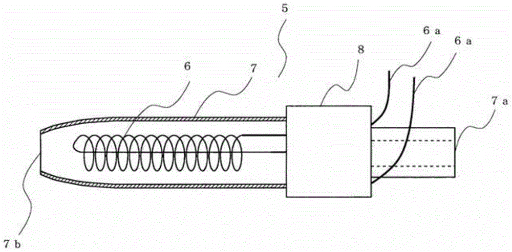
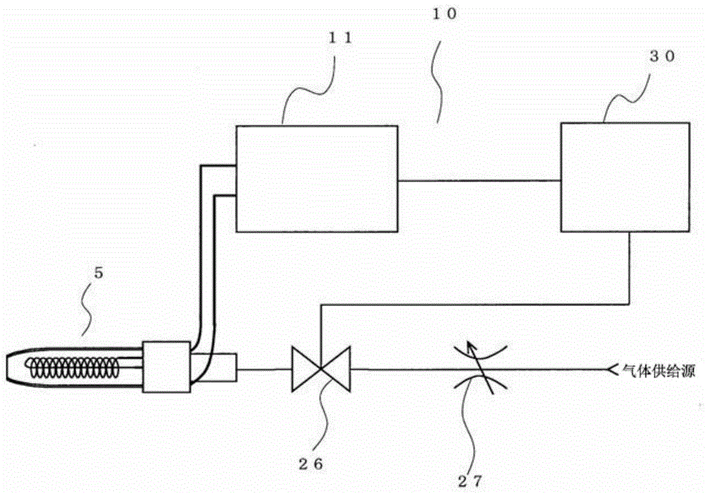
[0044] Embodiments of the wire bonding apparatus and the wire bonding method of the present invention will be described with reference to the following drawings. In addition, the present invention uses heated air or other gas (gas) and other gases that flow out from the ultra-small hot air heater installed on the bonding head or the bonding arm to heat the chips, substrates (lead frames), and balls (balls). ), the bonding tool or the bonding wire is heated, and the heated air or gas is supplied for a limited time in the necessary heating area for bonding, thereby improving the bonding performance, reducing the adverse effects of heating with the existing heating plate, and improving production. efficiency and quality.

[0045] The structure of the coupling device

[0046] figure 1 It is a structural schematic diagram of the bonding device of the present invention. Additionally, for Figure 8 The same structural parts of the conventional wire bonding apparatus shown are den...


PUM


Abstract

The present invention can improve bonding performance by supplying heated air or gas only for a limited time in the region necessary for bonding, reduce adverse effects of heating, and improve production efficiency and quality. The wire bonding apparatus includes: a case in which a heater is built in, the heater is made of a metal with a high temperature coefficient of resistance capable of instantaneous heating, and the case is formed to include a joint from a front end to a joint including a joint. The nozzle shape of the outlet for blowing hot air from the component and the inlet for compressed gas to flow in at the other end; a heating control device that heats the heater; a compressed gas supply control device that supplies , cutting off the compressed gas leading to the housing; the wire bonding apparatus is controlled to be capable of setting at least a period of time during which the bonding tool is not in contact with the bonding point from the The housing supplies the hot air to the joining member.

Description

technical field [0001] The present invention relates to a wire bonding device and a wire bonding method, and more particularly to a wire bonding device and a wire bonding method capable of stable bonding. Background technique [0002] It has been known for a long time that Figure 8 Shown is a wire bonding device (Wire bonding) as a bonding device for connecting electrodes (pad) on an IC chip (IC chip) and external pins (external lead). Figure 8 It is a schematic structural diagram of a conventional wire bonding device. [0003] Such as Figure 8 As shown, the conventional wire bonding apparatus 30 includes an ultrasonic horn (ultrasonic horn) 33, a bonding arm (bonding arm) 32, a bonding head (bonding head) 31, an XY table (XY station) 40, and a bonding table (bonding arm). Stee ge) 43, heating block (ヒータッロック) 45, control unit (control unit) 50 and drive unit (drive unit) 55, the ultrasonic horn includes an ultrasonic vibrator (not shown in the figure) and capillary (capil...

Claims


Application Information

Patent Timeline
Patent Type & Authority Patents(China)
IPC IPC(8): H01L21/60
CPCH01L24/78H01L24/85H01L24/45H01L2224/45139H01L2224/45147H01L2224/45144H01L2224/85H01L2224/78253H01L2224/78301H01L2924/01047H01L2924/01015H01L2924/00014H01L2924/00H01L2924/00015H01L2224/48H01L2224/48247H01L2224/789H01L2224/859B23K20/007H01L2924/1306H01L2924/12041H01L2924/15747H01L2224/85205H01L2224/78252H01L2924/00011H01L2924/01049H01L23/48H01L22/00B23K9/0008
Inventor 杉藤哲郎
Owner KAIJOO KK
Features
  • R&D
  • Intellectual Property
  • Life Sciences
  • Materials
  • Tech Scout
  • Unparalleled Data Quality
  • Higher Quality Content
  • 60% Fewer Hallucinations
Learn More