
Metallic surface dirt laser cleaning system and method

A technology of laser cleaning and metal surface, which is applied in the field of laser cleaning to achieve the effect of good cleaning effect, reduced energy loss and low cost

Active Publication Date: 2014-05-28
武汉翔明激光科技有限公司
View PDF8 Cites 87 Cited by
  • Summary
  • Abstract
  • Description
  • Claims
  • Application Information

AI Technical Summary

Problems solved by technology

[0006] In view of the above defects and improvement needs of the prior art, the present invention provides a metal surface dirt laser cleaning system and method, thereby solving the problem of high-efficiency and high-quality cleaning of the dirt layer on the surface of the metal substrate, thereby obtaining The original surface roughness of the material and the cleaning surface of the metal luster achieve the ideal cleaning effect and cleaning efficiency

Method used


Image

  • Metallic surface dirt laser cleaning system and method
  • Metallic surface dirt laser cleaning system and method
  • Metallic surface dirt laser cleaning system and method

Examples


example 1

[0046] Example 1: Cleaning of metal paint on the surface of aluminum alloy body

[0047] Continuous laser light emitted by fiber laser

[0048] Paint layer thickness: 0.50mm

[0049] Laser power: 300w

[0050] Cleaning speed: 500mm / s

[0051] Spot diameter: 0.07mm

[0052] Air flow: 3.5m 3 / h

[0053] Under microscopic observation, ≧95% of the paint layer is removed, cleaning efficiency: 115.4mm 2 / s, compared with the existing ultrasonic cleaning efficiency of the same thickness of metal paint layer is generally only 40-50mm 2 / s; In addition, the base material is not damaged after cleaning, and the original bright white color of the aluminum alloy is exposed on the surface, achieving the ideal effect of cleaning.

example 2

[0054] Example 2: Rust layer cleaning on the surface of 45 steel

[0055] Continuous laser light emitted by fiber laser

[0056] Rust layer thickness: 0.45mm

[0057] Laser power: 250w

[0058] Cleaning speed: 500mm / s

[0059] Spot diameter: 0.07mm

[0060] Air flow: 3.0m 3 / h

[0061] Under microscopic observation, ≧95% of the rust layer is removed, cleaning efficiency: 89.8mm 2 / s. The base material is not burned, and the metal color of carbon steel is exposed, achieving the ideal effect of cleaning.

example 3

[0062] Example 3: Cleaning of oil stain layer on stainless steel plate

[0063] Using truncated pulsed laser

[0064] Oil layer thickness: 0.05mm

[0065] Laser power: 200w

[0066] Cleaning speed: 500mm / s

[0067] Spot diameter: 0.07mm

[0068] Air flow: 1.0m 3 / h

[0069] Under microscopic observation, ≧95% of the oil layer is removed, cleaning efficiency: 122.2mm 2 / s. There is no damage to the stainless steel plate, and the original metal color of the stainless steel substrate is exposed, achieving the ideal effect of cleaning.

[0070]Therefore, the metal surface laser cleaning method based on the fiber laser proposed in the present invention breaks the limitation that the power density can only be increased by increasing the power in the early stage, but uses a fiber laser with a small beam diameter and stable quality, and adjusts the beam system to achieve the ideal spot diameter. While increasing the power density, it does not affect the change of heat input...


PUM

PropertyMeasurementUnit
Thicknessaaaaaaaaaa

Abstract

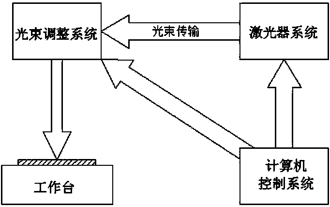
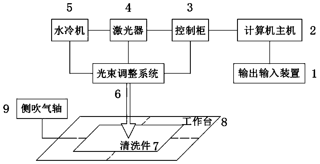
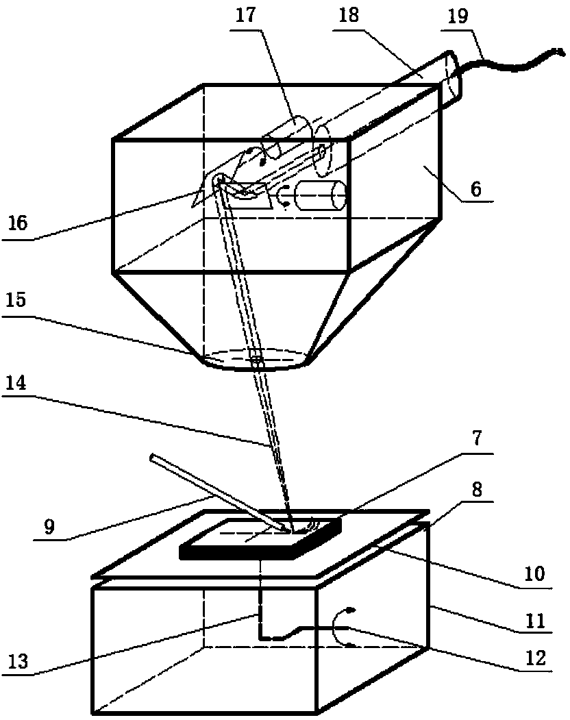
The invention discloses a metallic surface dirt laser cleaning system and method. The metallic surface dirt laser cleaning system comprises a computer control system, a laser system and a light beam adjustment system. The computer control system controls the laser system to enable light beams to be emitted from a laser of the laser system and enable the light beams to enter the light beam adjustment system through optical fiber transmission. Meanwhile, the computer control system is also used for controlling the light beam adjustment system and adjusting the spot diameter of the light beams so that the adjusted light beams can be shot regularly onto the surface of a metal part to be cleaned and carry out cleaning on dirt on the surface of the metal part to be cleaned.

Description

technical field [0001] The invention belongs to the technical field of laser cleaning, and in particular relates to a laser cleaning system and method for metal surface dirt. Background technique [0002] Metal substrates are common objects in industrial cleaning, such as metal molds, weld surfaces, body shells, aircraft skins, etc. The commonly used materials for these metal substrates are usually stainless steel, carbon steel and aluminum alloy, which are prone to oil stains, rust layers, and residual paint in practical applications, which will lead to changes in their surface roughness and mechanical properties, affecting actual performance. Therefore, the surface needs to be cleaned after a period of use or before surface pretreatment. Due to the particularity of the cleaning object, cleaning dirt, cleaning process and cleaning requirements, metal cleaning is different from general chemical cleaning and soft surface cleaning. [0003] Although there are many types of t...

Claims


Application Information

Patent Timeline
IPC IPC(8): B08B7/00
CPCB08B7/0042
Inventor 王春明俞鸿斌胡席远王军
Owner 武汉翔明激光科技有限公司
Learn More