A vehicle-mounted fully automatic intelligent hydraulic workover rig with tubing strings placed vertically
What is Al technical title?
Al technical title is built by PatSnap Al team. It summarizes the technical point description of the patent document.
A tubing string, fully automatic technology, applied in the direction of drill pipe, casing, drilling equipment, etc., can solve the problems of high noise, high labor intensity, low mechanical efficiency, etc., to reduce environmental pollution, save workover sites, and improve work efficiency efficiency effect
Active Publication Date: 2017-02-01
山东科瑞石油装备有限公司
View PDF9 Cites 1 Cited by
Summary
Abstract
Description
Claims
Application Information
AI Technical Summary
This helps you quickly interpret patents by identifying the three key elements:
Problems solved by technology
Method used
Benefits of technology
Problems solved by technology
[0005] ①The power system of small workover rigs with rotary hoist is driven by diesel engine, which has high installed power, high energy consumption and high noise
[0006] ②The hoisting system of small workover rigs with rotary hoisting adopts a rotary hoisting and lowering mechanism, which has complex kinematic pairs and low mechanical efficiency
[0007] ③The hoisting system of linear hoisting small workover rigs has a complex structure and a low degree of automation
[0008] ④ Rotary hoisting and linear hoisting small workover rigs can only lift and release a single oil pipe, which takes a long time to lift and release the oil pipe, with high labor intensity and low efficiency
[0009] ⑤ The small workover rigs of the rotary lifting type and the linear lifting type all discharge a single oil pipe horizontally on the ground, and the working time for placing the oil pipe is long, the labor intensity is high, and the efficiency is low
[0010] ⑥ Rotary hoisting and linear hoisting small workover rigs cannot implement automatic control and long-distance offline operation
Method used
Image
Click on the blue label to locate the original text in one second.
Reading with bidirectional positioning of images and text.
Examples
Embodiment Construction
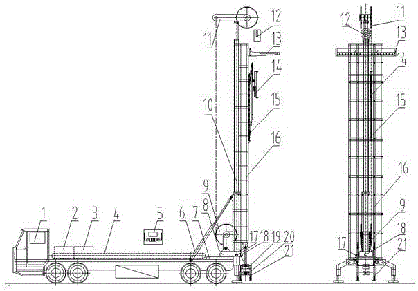
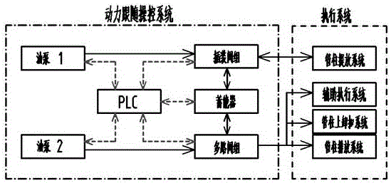
[0016] A vehicle-mounted full-automatic intelligent hydraulic workover rig for vertically placing tubing strings, which is composed of a vehicle-mounted chassis 1, a combined hydraulic power source 2, an intelligent power drive system 3, a hydraulic automatic energy storage system 4, an offline control panel 5, and a luffing cylinder 6 , fixed support 7, movable support 8, rope wheel distance increasing system 9, single-cylinder lifting system 10, balanced sky wheel system 11, automatic swimming lifting pipe system 12, pipe column discharge rack 13, automatic pipe grasping system 14 , automatic pipe transfer system 15, lifting support frame 16, wellhead automatic centering mechanism 17, tubing length automatic measuring mechanism 18, tubing automatic make-up and breakout device 19, tubing automatic wellhead plate 20, and multifunctional wellhead tubing seat 21. It is characterized in that the mechanism is divided into five major systems: vehicle luffing and support system, oil ...
PUM
Abstract
A tubing string vertical vehicular full-automatic smart hydraulic workover rig comprises a vehicular chassis, a hydraulic power source, a smart power drive system, a hydraulic automatic energy accumulation system, an offline operating plate, a variable-amplitude oil cylinder, a fixed support, a movable support, a rope sheave distance increasing system, a single cylinder lifting system, a balance head sheave system, an automatic suspension tube lifting system, a tubing string arranging rack, an automatic tube gripping system, an automatic tube moving system, a lifting support frame, a wellhead automatic centering mechanism, an oil pipe length automatic measuring mechanism, an oil pipe automatic fastening and unfastening device, an oil pipe automatic wellhead plate and a multifunctional wellhead oil pipe seat. The tubing string vertical vehicular full-automatic smart hydraulic workover rig is characterized by comprising a vehicular variable-amplitude support system, a tubing string automatic lifting system, a oil pipe automatic fastening and unfastening system and an electric-hydraulic supplying, driving and operating system. By the tubing string vertical vehicular full-automatic smart hydraulic workover rig, oil pipe lifting time is shortened greatly, and work efficiency is increased.
Description
technical field [0001] The invention relates to a vehicle-mounted fully automatic intelligent hydraulic workover rig for vertically placing oil pipe strings, in particular to a workover rig for oil and water well construction operations in oil fields, and belongs to the technical field of advanced manufacturing of oil drilling and workover equipment. Background technique [0002] The most common oilfield workover techniques at home and abroad are roughly divided into two categories: major workover and minor workover according to the complexity of oil and water well operations. The corresponding workover rigs are also roughly divided into There are two categories of large workover rigs and small workover rigs: the overhaul operation mainly solves the complex salvage of oil and water wells in oil fields, the repair of oil well casings, and drilling inside the casing. Most of them are large-scale heavy-duty workover equipment with complete functions; minor repair operations are...
Claims
Application Information
Patent Timeline
Application Date:The date an application was filed.
Publication Date:The date a patent or application was officially published.
First Publication Date:The earliest publication date of a patent with the same application number.
Issue Date:Publication date of the patent grant document.
PCT Entry Date:The Entry date of PCT National Phase.
Estimated Expiry Date:The statutory expiry date of a patent right according to the Patent Law, and it is the longest term of protection that the patent right can achieve without the termination of the patent right due to other reasons(Term extension factor has been taken into account ).
Invalid Date:Actual expiry date is based on effective date or publication date of legal transaction data of invalid patent.