High voltage crosslinked cable test power supply based on FPGA

A technology for cross-linked cables and power testing, which is applied to testing circuits, testing dielectric strength, and measuring electricity. It can solve problems such as difficult microprocessor control, unstable waveforms, and drift, and achieve small power supply capacity requirements and improved control. Accuracy, suitable for on-site use

Inactive Publication Date: 2014-05-28
南京冠亚电源设备有限公司
View PDF8 Cites 12 Cited by
  • Summary
  • Abstract
  • Description
  • Claims
  • Application Information

AI Technical Summary

Problems solved by technology

However, the biggest disadvantage of this type of chip is that the waveform is unstable, it will be affected by the electromagnetic field and the working environment, the drift phenomenon is serious, and it is not easy to be controlled by a microprocessor, and it is difficult to dynamically adjust the frequency and power.
At the same time, when the natural frequency of the inverter load changes, if the operating frequency of the inverter cannot be changed at this time, the inverter will deviate from the optimal operating point, which not only makes the switch on the bridge arm of the inverter The switching loss of the device increases, and when the inverter is far away from the load resonance point, under a certain Q value, the load impedance will also increase, so that the power capacity of the inverter cannot be fully utilized, and the work efficiency will decrease.

Method used


Image

  • High voltage crosslinked cable test power supply based on FPGA
  • High voltage crosslinked cable test power supply based on FPGA
  • High voltage crosslinked cable test power supply based on FPGA

Examples


Embodiment Construction

[0015] The technical solutions of the present invention will be further described through specific embodiments below in conjunction with the accompanying drawings.

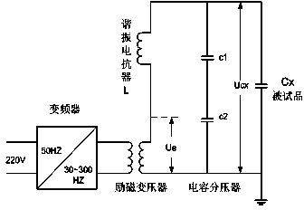
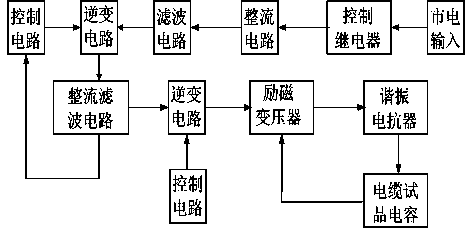
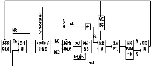
[0016] Such as figure 1 , figure 2 , image 3 as shown, figure 1 It is a working principle diagram of the present invention; figure 2 It is a structural block diagram of the main circuit of the present invention; image 3 Design a block diagram for the control circuit in the present invention.

[0017] The FPGA-based high-voltage cross-linked cable test power supply of this embodiment consists of a control circuit, an inverter circuit, a filter circuit, a rectifier circuit, a control relay, a rectifier filter circuit, an excitation transformer, a resonant reactor, and a cable test capacitor. It is: the AC 220V, 50HZ power supply outputs 30-300HZ frequency adjustable voltage through the frequency converter, input it to the excitation transformer, boosts the voltage to 0-2000V, and then passes through the res...


PUM


Abstract

The invention provides a high voltage crosslinked cable test power supply based on the FPGA. A control relay, a rectifying circuit, a filter circuit, an inverter circuit, an exciting transformer and a resonance electric reactor are sequentially connected to form the high voltage crosslinked cable test power supply. The inverter circuit is controlled by the control circuit. An alternating-current power supply outputs adjustable alternating voltages through a frequency converter and inputs the adjustable alternating voltages to the exciting transformer. The adjustable alternating voltages are inputted into a resonance circuit composed of the resonance electric reactor, a cable tested product capacitor and the exciting transformer after being boosted. The high voltage crosslinked cable test power supply can conduct withstand voltage tests on XLPE cables with different lengths by means of the series resonance circuit, intelligent control over automatic frequency tracking is achieved through the FPGA so that the control accuracy of the system can be improved, the high voltage crosslinked cable test power supply has the advantages of being light in weight, small in requirement for power supply capacity, simple in control structure, convenient to control, quite suitable for field use and the like, the voltage borne on a cable tested product stably rises to 18 kV under the condition that the output power is 6 kW, and the withstand voltage test requirement for the crosslinked polyethylene cable under the voltage below 18 kV is met.

Description

technical field [0001] The invention relates to the field of a high-voltage test power supply, in particular to a high-voltage cross-linked cable test power supply based on a series resonant circuit. [0002] Background technique [0003] With the continuous implementation of urban reconstruction projects, more and more high-voltage power cables are used, among which rubber-plastic insulated cables mainly represented by cross-linked polyethylene cables are most commonly used. It uses chemical methods to transform polyethylene with a linear molecular structure into a cross-linked polyethylene with a three-dimensional network structure, thereby greatly improving the mechanical-thermal properties of the cable, while maintaining the good electrical properties of the cable. XPLE cable is the abbreviation of cross-linked polyethylene insulated cable. XLPE cables have many advantages such as light weight, easy installation, good thermal performance, large transmission capacity, r...

Claims


Application Information

Patent Timeline
Patent Type & Authority Applications(China)
IPC IPC(8): G01R1/28G01R31/14
Inventor 张海波黄锐孙邦伍王兆明王海娥
Owner 南京冠亚电源设备有限公司
Why Eureka
Try Eureka