
Installing structure of liquid tank of large liquefied gas carrier and installation locating method of liquid tank

A liquefied gas ship and installation structure technology, applied to large containers, packaging, hulls, etc., can solve the problems of large differences in installation and positioning methods for liquid filling installation and positioning methods, small tank volume, etc., and achieve low tooling requirements and easy operation easy effect

Active Publication Date: 2014-06-04
JIANGNAN SHIPYARD GRP CO LTD
View PDF6 Cites 52 Cited by
  • Summary
  • Abstract
  • Description
  • Claims
  • Application Information

AI Technical Summary

Problems solved by technology

At present, small-scale liquefied gas ships have been successfully built in China, but their tanks are small tanks with small volumes, and their installation and positioning methods are quite different from those of large-scale liquefied gas ships. The installation and positioning method of the liquid tank of the ship is still in the exploratory stage, so in order to provide technical support for the construction of the large-scale liquefied gas ship and ensure the successful construction of the ship, it is necessary to study the liquid tank installation structure and its installation and positioning method of the large-scale liquefied gas ship. Make breakthroughs to meet existing production needs

Method used


Image

  • Installing structure of liquid tank of large liquefied gas carrier and installation locating method of liquid tank
  • Installing structure of liquid tank of large liquefied gas carrier and installation locating method of liquid tank
  • Installing structure of liquid tank of large liquefied gas carrier and installation locating method of liquid tank

Examples


Embodiment Construction

[0048] The structure, ratio, size, etc. shown in the drawings of the specification are only used to match the content disclosed in the specification for the understanding and reading of those familiar with this technology, and are not used to limit the implementation of the present invention. The technical significance, any structural modification, proportional relationship change or size adjustment, shall still fall within the technical content disclosed in the present invention without affecting the effects and objectives that can be achieved by the present invention Can cover the range. At the same time, terms such as "upper", "lower", "front", "rear", "middle" and other terms cited in this specification are only for ease of description and are not used to limit the scope of the present invention. , The change or adjustment of its relative relationship shall be regarded as the scope of the implementation of the present invention without substantial change of the technical co...


PUM


Abstract

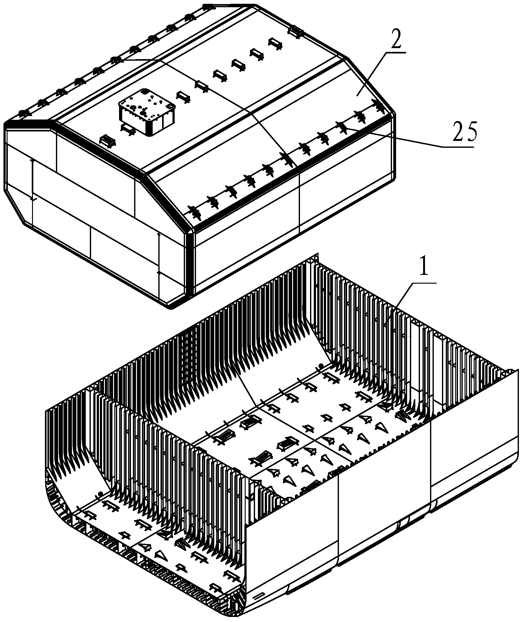
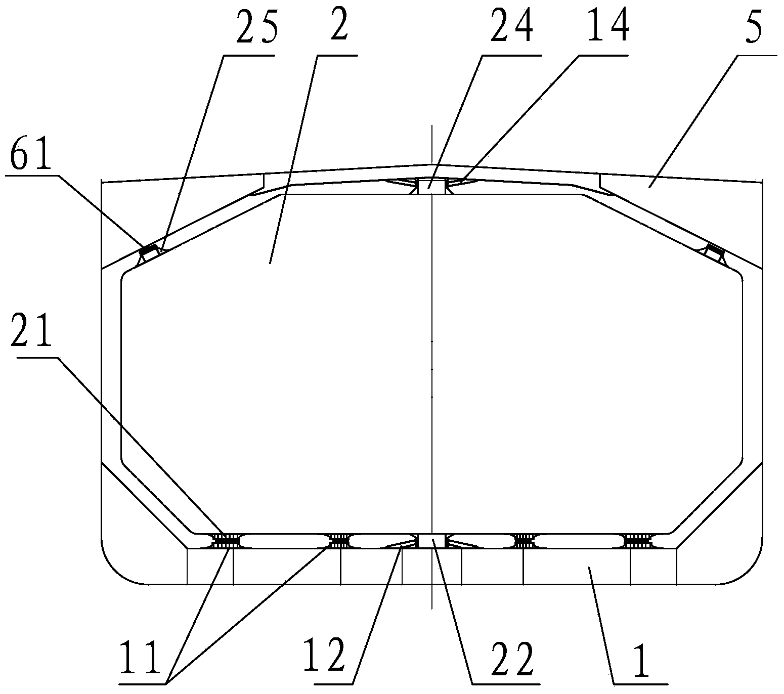
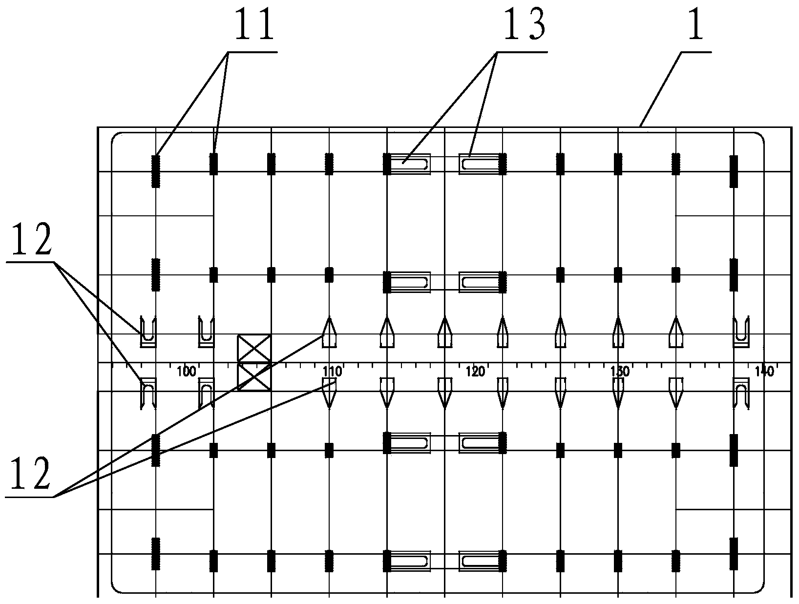
The invention provides an installing structure of a liquid tank of a large liquefied gas carrier and an installation locating method of the liquid tank. According to the installing structure of the liquid tank of the large liquefied gas carrier, a liquid tank cabin of the large liquefied gas carrier is mainly provided with a bottom perpendicular supporting base, a bottom transverse-shake preventing support, a top transverse-shake preventing support and a bottom longitudinal-shake preventing support, wherein the bottom perpendicular supporting base is used for supporting a whole liquid tank, the bottom transverse-shake preventing support and the top transverse-shake preventing support are used for preventing the liquid tank from transversely shaking relative to a hull, and the bottom longitudinal-shake preventing support is used for preventing the liquid tank from longitudinally shaking relative to the hull. In the actual working process of installing the liquid tank in the liquid tank cabin, according to the installation locating method of the liquid tank, the data collection step, the three-dimensional simulation step, the epoxy resin thickness calculation step, the locating datum line assignment step, the supporting positioning step and the like are carried out in sequence, and finally the liquid tank is installed in the liquid tank cabin. By the adoption of the installation locating method of the liquid tank, installation locating work of the liquid tank can be rapidly and accurately accomplished, the utilization rate of tools is high, the using time of a crane is short, and the construction cost of an enterprise is greatly reduced.

Description

Technical field [0001] The invention relates to a method for installing a liquid tank of a liquefied gas ship, in particular to a method for installing and positioning a liquid tank through a surveying and mapping device. Background technique [0002] At present, the domestic shipbuilding industry is developing in the direction of products with high added value, high technology content, and high construction difficulty. Large-scale liquefied gas ships are also one of them. [0003] Liquefied gas ships are liquid cargo ships that specialize in transporting liquefied gas. Generally, they can be divided into liquefied natural gas ships and liquefied petroleum gas ships. The key technology of the liquefied gas ship is concentrated in the liquid tank area, and the hoisting and positioning of the liquid tank is one of the key technologies in the construction of this type of ship. Whether the hoisting can be effectively controlled directly determines the success of the ship's construction...

Claims


Application Information

Patent Timeline
IPC IPC(8): B63B11/00B63B25/00B65D88/02
Inventor 苏龙姜旭枫黄智焱刘磊刘保华陆劲宇胡璐于东
Owner JIANGNAN SHIPYARD GRP CO LTD
Learn More