
Airtightness automatic test system and test method

An automatic test system and air-tightness testing technology, applied in the direction of using liquid/vacuum for liquid-tightness measurement, and by measuring the acceleration and deceleration rate of fluid, etc. Less problems, to shorten the time of air tightness test, improve the level and accuracy, and ensure the effect of traceability

Inactive Publication Date: 2014-06-04
赛龙通信技术(深圳)有限公司
View PDF6 Cites 27 Cited by
  • Summary
  • Abstract
  • Description
  • Claims
  • Application Information

AI Technical Summary

Problems solved by technology

[0002] Existing waterproof and airtight detection technology for shell assembly components of digital products such as mobile phones uses air blowing from the inside to simulate the pressure of the product in water. The pressure situation is opposite, which affects the test results. At the same time, the existing waterproof mobile phone shell assembly component airtightness testing technology uses the method of bubbling to observe whether the product leaks, and judges whether the component is leaking according to the number of bubbling. This judgment method is subjective. Strong, non-quantifiable, easy to misjudgment; on the other hand, the existing airtight testing equipment for waterproof mobile phone shell assembly components does not have airtight test fixtures, which are manually operated, and the test efficiency is low; at the same time, the existing waterproof mobile phone shell assembly components The air tightness testing equipment has low precision, and the test precision is 0.1InH 2 O scale air pressure change
Moreover, the existing test method is a single test for a long time, and the test result can only be known after the end of the test time. The efficiency is low, and the test condition is single, which also affects the accuracy of the test result

Method used


Image

  • Airtightness automatic test system and test method
  • Airtightness automatic test system and test method
  • Airtightness automatic test system and test method

Examples


Embodiment Construction

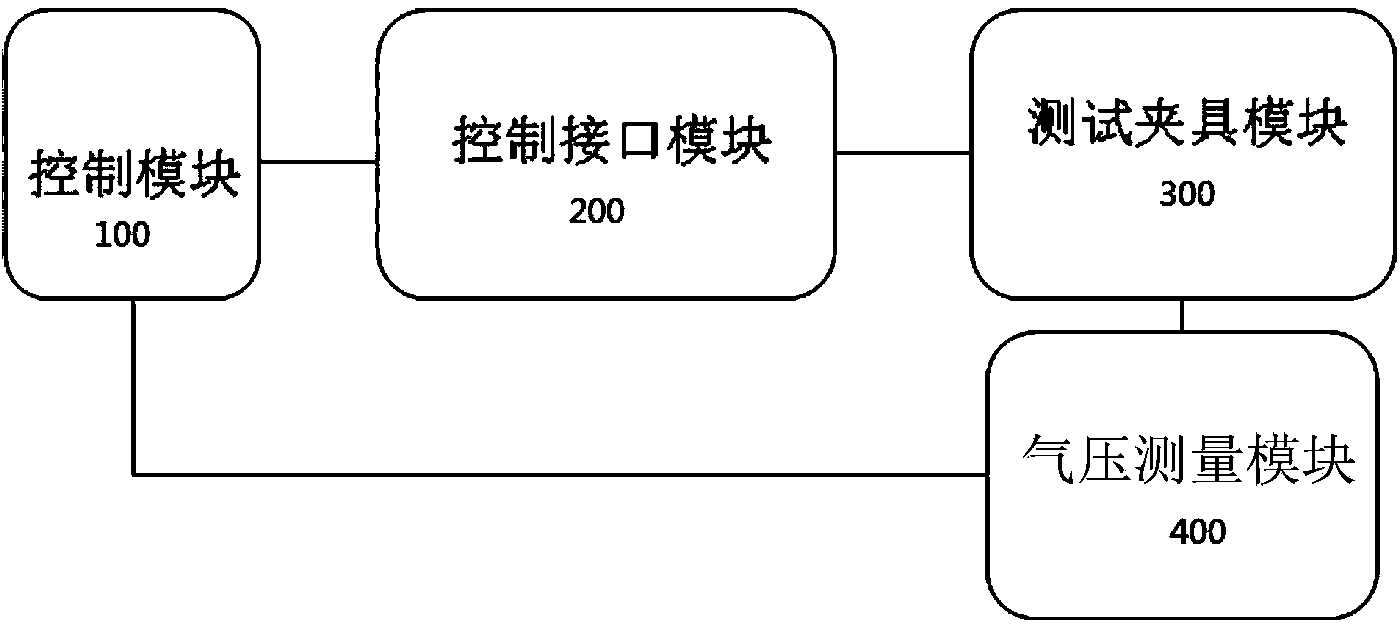
[0037] refer to figure 1 As shown, the present invention provides an automatic airtightness test system, which includes: a control module 100 for integrated control of the work of each functional module; a control interface module 200 for communicating with the control module 100; a test fixture module 300 for Communicatively connected with the control interface module 200; the air pressure measurement module 400 is respectively communicatively connected with the test fixture module 300 and the control module 100; For air pumping detection, the air pressure value is read from the test fixture module 300 through the air pressure measurement module 400, and the leakage measurement value calculated according to the current air pressure value in each specified time period is compared with the set maximum leakage amount, according to The time-period comparison result is fed back to the control module 100 and the test detection result is output. Among them, the relationship between...


PUM


Abstract

Disclosed is an airtightness automatic test method which includes the following steps: (1) a to-be-tested product is placed on a lower die of a test clamp module of the airtightness test system and a control module drives an upper die to descend so as to press tightly the to-be-tested product so that a sealed cavity is formed between the to-be-tested product and the lower die; (2) the control module controls a vacuum pumping and air pressure measurement module to extract air from the sealed cavity via an air extraction hole until a specified time so as to generate a negative pressure; (3) within a specific air pressure test time, air pressure changes in the sealed cavity are measured at different periods and leakage measurement values which are calculated according to current air pressure values at different time periods are compared with maximum leakage quantities which are set respectively so that the qualified rate of the to-be-tested product is controlled according to the time-slice comparison result.

Description

technical field [0001] The invention relates to the technical field of airtightness detection, in particular to the waterproof and airtightness test of casing assembly components of digital products such as mobile phones. Background technique [0002] Existing waterproof and airtight detection technology for shell assembly components of digital products such as mobile phones uses air blowing from the inside to simulate the pressure of the product in water. The pressure situation is opposite, which affects the test results. At the same time, the existing waterproof mobile phone shell assembly component airtightness testing technology uses the method of bubbling to observe whether the product leaks, and judges whether the component is leaking according to the number of bubbling. This judgment method is subjective. Strong, non-quantifiable, easy to misjudgment; on the other hand, the existing airtight testing equipment for waterproof mobile phone shell assembly components does ...

Claims


Application Information

Patent Timeline
Patent Type & Authority Applications(China)
IPC IPC(8): G01M3/32
Inventor 叶德潜朱永球陈志朋
Owner 赛龙通信技术(深圳)有限公司
Learn More