Annular welding method

A technology of annular welding and welding current, applied in welding equipment, laser welding equipment, plasma welding equipment, etc., can solve the problems of air leakage at the interface, surface clamping damage, poor neutrality, etc., to prevent over-burning or burn-through , to ensure the effect of welding sealing and quality improvement

Active Publication Date: 2014-06-11
佛山晓世科技服务有限公司
View PDF9 Cites 32 Cited by
  • Summary
  • Abstract
  • Description
  • Claims
  • Application Information

AI Technical Summary

Problems solved by technology

[0005] However, there are other problems with the above process: flash welding needs to clamp the various parts of the shell to implement the upsetting force and reach a certain upsetting speed, which is easy to cause clamping damage on the surface; if the shell adopts the above (2) In the case of this structure, due to the limitation of the flash welding process, the parts will be separated and approached during welding, and the three parts cannot be welded at the same time, and the welding needs to be performed twice; due to the multiple separation, contact, and alignment of each part, the welding The time neutrality is poor; due to the upsetting force, the molten iron at the welding part of each part is extruded to both sides, so that the inner and outer surfaces of the shell welding part have raised foreign objects; the welding power is required, so the equipment investment is large; welding The strength is difficult to control. For example, when welding, each part is close to separation, the heat is unstable, and the welding quality is also unstable. Moreover, the thermal stress is large and the impact force is large, which is easy to cause lattice fracture and thermal cracks.
Since the weld seam is 360° circular, if the welding is just equal to 360° from the arc start point to the arc end point, the interface is prone to air leakage due to incomplete sealing
If the welding is greater than 360° from the arc start point to the arc end point, the above problems can be solved. However, because the traditional welding process is adopted, a constant current is used for welding from the arc start point to the arc end point. When the workpiece rotates through 360° , after the position of the arc starting point passes through the welding torch again, the position where the welding torch is aimed at is the weld seam that has been completely welded. At this time, the large welding current will cause overburning, the welding place will turn black, and even burn through the welded seam weld seam
Therefore, it is difficult to guarantee the welding quality of the circular weld at present, resulting in a low product qualification rate

Method used


Image

  • Annular welding method
  • Annular welding method
  • Annular welding method

Examples


Embodiment 1

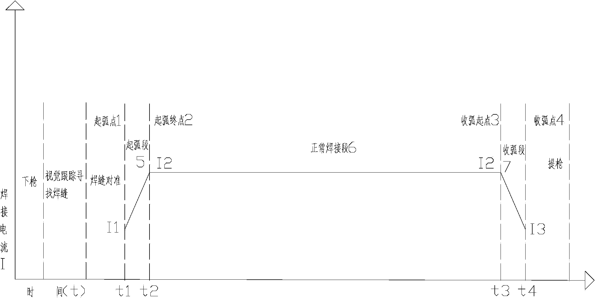
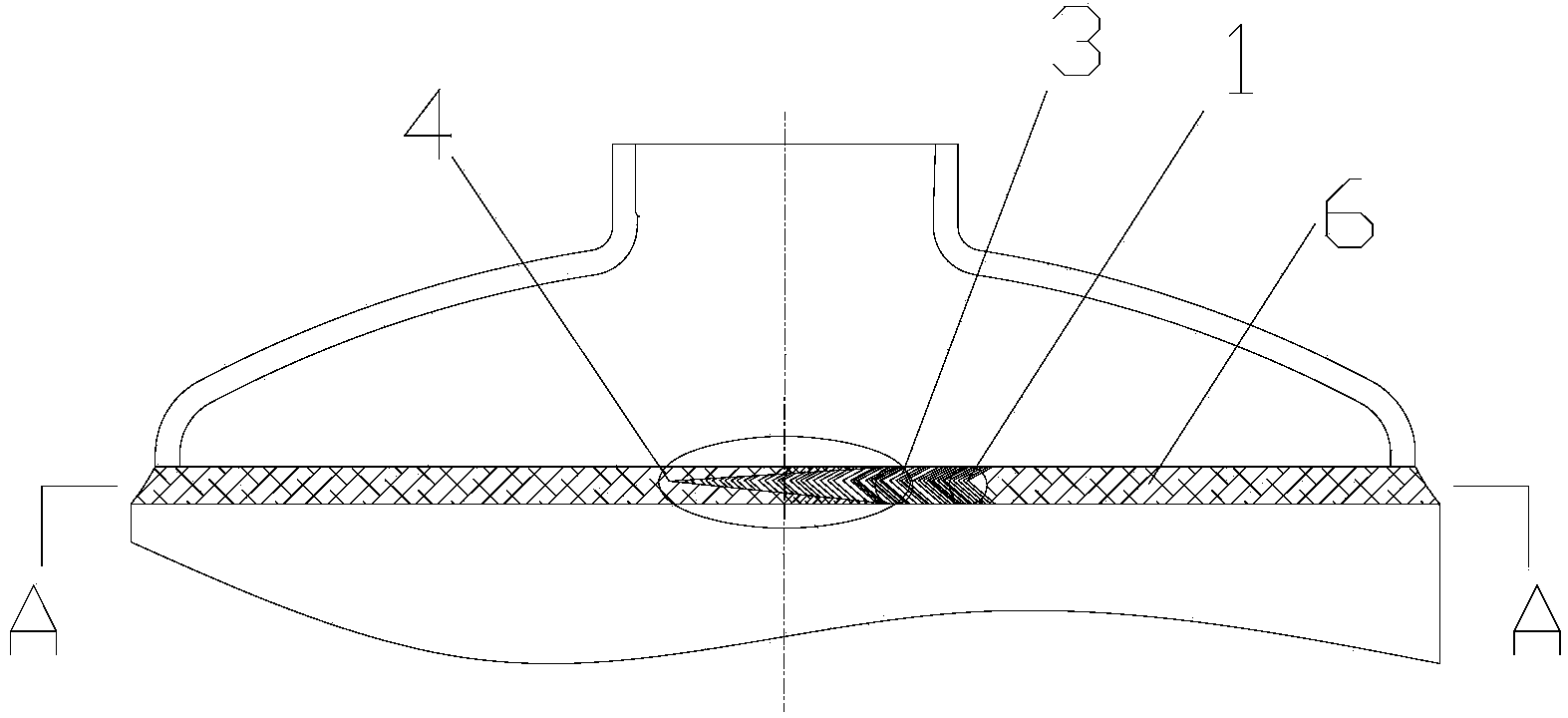
[0036] process such as Figure 5 As shown, the production equipment such as Image 6 shown. First, when the welding workpiece 11 is installed on the welding machine, the tooling module of the welding machine starts to detect whether the welding workpiece 11 is in place, whether the clamping welding workpiece 11 is completed, starts to drive the welding workpiece 11 to rotate, and the welding torch 8 begins to descend and align. At this time, the camera mechanism 611 starts to collect signals, and the visual control module 612 starts to identify the welding seam and the arc starting point and controls the welding torch 8 to align with the welding seam. The welding power supply module 613 controls the welding current of the welding torch 8, press figure 1 The welding curve is welded.

[0037] The welding workpiece 11 rotates slowly, and the visual tracking system captures the welding torch 8 and the weld seam, and adjusts the relative position of the welding torch 8 to complet...

Embodiment 2

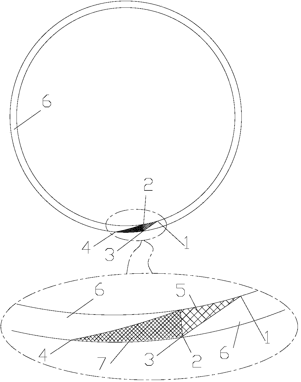
[0043] In this example, if Figure 4 As shown, the welding workpiece 11 rotates slowly, the visual tracking system captures the welding torch 8 and the weld seam, and adjusts the relative position of the welding torch 8 to complete the alignment, and then outputs a signal to the welding power source 613 to start the arc. The current at arc starting point 1 is I1, and the time point is t1, the welding workpiece 11 rotates, and after a period of time to time point t2, the position of the welding seam aligned with the welding torch 8 is from the arc starting point 1 to the arc starting end point 2, and the welding current in the arc starting section 5 gradually changes linearly from I1 As large as the normal welding section 6 welding current value I2, where I1 is about 60% of I2;

[0044] The welding workpiece 11 continues to rotate. After a period of time, the time point t3 is reached. At this time, the welding seam is aligned with the position of the welding torch 8 from the ar...


PUM


Abstract

The invention relates to an annular welding method. A welding gun is adopted to realize welding; a welding line of a workpiece is annular. The annular welding method is characterized in that welding comprises arc striking, normal welding and arc stopping; the welding current of an arc striking section between an arc striking point and an arc striking end point and the welding current of an arc stopping section between an arc stopping start point and an arc stopping point are lower than that of the normal welding; furthermore, the welding line of the welding line from the arc striking point to the arc stopping point rotates around an angle which is larger than 360 degrees. Due to a research, the quality of the annular welding line is greatly improved by changing welding technical parameters by the adoption of soft arc striking and soft arc stopping, so that the welding sealing property of end-to-end overlapped sections of the welding line formed in the arc striking and the arc stopping is guaranteed; the problem of welding missing is avoided; meanwhile, the phenomenon of burnthrough during welding is avoided, and the end-to-end overlapped section of the welding line is smoothly transitioned. The annular welding method is particularly suitable for welding on a barrel body or a pipe body with a high sealing requirement.

Description

technical field [0001] The invention relates to the field of welding, in particular to a ring welding method. Background technique [0002] In the field of welding, metal welding is very common. After years of development, the welding process has basically matured. For example, compressor liquid receiver, air conditioner muffler, gas-liquid separator for central air conditioner, oil-gas separator for central air conditioner, fire extinguisher, gas storage tank and other products, the shells of which are all welded. Another example is the connection of some pipes, including the connection of the same metal pipes or the connection of dissimilar metals, which can be realized by welding. [0003] Taking the liquid accumulator of a compressor as an example, its shell is generally made of iron materials, and generally has two structures: (1) The shell is divided into two parts, the upper half and the lower half, and the inner diameter of the welding end of one part is larger tha...

Claims


Application Information

Patent Timeline
Patent Type & Authority Applications(China)
IPC IPC(8): B23K9/028B23K9/127B23K9/095B23K9/28B23K9/16B23K9/18B23K10/02B23K26/28B23K26/08B23K26/70
CPCB23K9/028B23K9/095B23K9/1274B23K9/16B23K9/173B23K9/186B23K10/02B23K26/044B23K26/28
Inventor 谢二文
Owner 佛山晓世科技服务有限公司
Why Eureka
Try Eureka