Detection method and three-phase permanent magnet synchronous motor

A technology of permanent magnet synchronous motor and detection method, which is applied in the direction of control of generator, motor generator control, electronic commutation motor control, etc., can solve problems such as circuit structure complexity, and achieve the effect of suppressing complexity

Inactive Publication Date: 2014-06-11
NIPPON DENSAN CORP
View PDF7 Cites 20 Cited by
  • Summary
  • Abstract
  • Description
  • Claims
  • Application Information

AI Technical Summary

Problems solved by technology

As a result, the circuit structure will be complicated

Method used


Image

  • Detection method and three-phase permanent magnet synchronous motor
  • Detection method and three-phase permanent magnet synchronous motor
  • Detection method and three-phase permanent magnet synchronous motor

Examples


Embodiment Construction

[0054] Hereinafter, exemplary embodiments of the present invention will be described with reference to the drawings.

[0055]

[0056] The motor of this embodiment detects the initial position of the rotor using a transient response when a pulse current is supplied to the coil. Therefore, first, the transient response of the coil will be described.

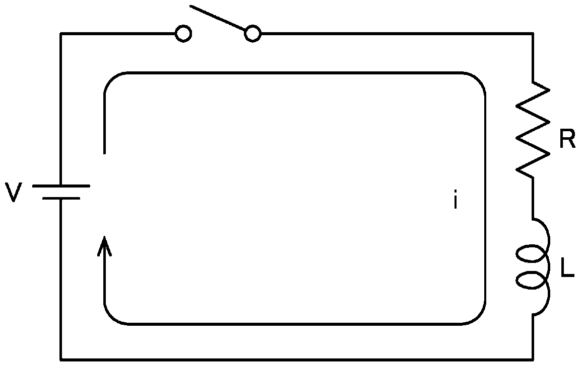
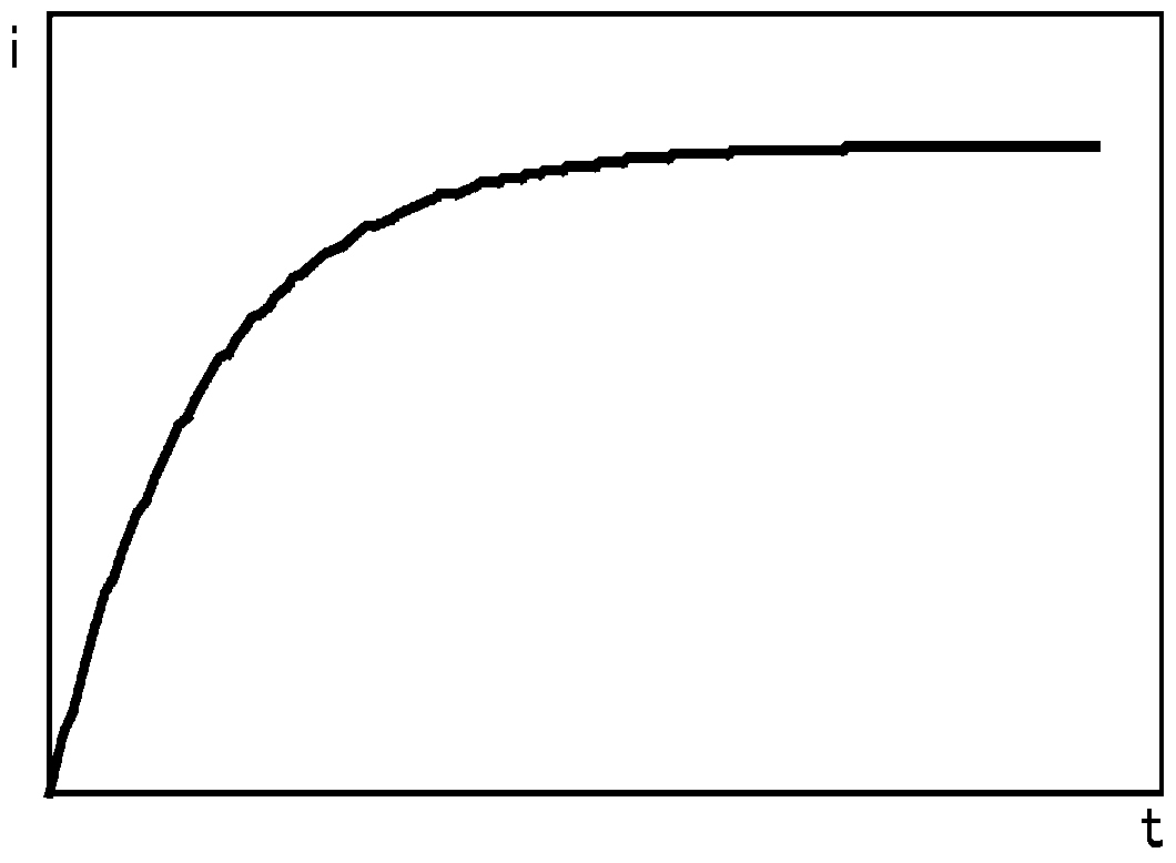
[0057] Each coil of the motor can be regarded as an RL series circuit in which the resistance R and the inductance L are connected in series. figure 1 It is a diagram showing an example of an RL series circuit. If a voltage V is applied to the RL series circuit, the current passing through the circuit will gradually increase due to the influence of the inductance L. And, if enough time passes, the current passing through the circuit reaches a maximum value of I=V / R. figure 2 is a graph showing the temporal change of this transient current. The magnitude of the transition current i after the time t has elapsed from the appli...


PUM


Abstract

The invention provides a detection method and a three-phase permanent magnet synchronous motor. With regard to the combinations of UV, UW and WU which are selected from three coils corresponding to the three phases, pulse currents are switched on along a direction and another direction, the magnitude of transition currents is detected when a certain time passes after the pulse currents are switched on, and the detected values are obtained. In addition, in dependence on the acquired magnitude relations among the detected values of a plurality of transition currents, and the circumferential initial position of a magnetic pole of a rotor relative to each coil of the three phases before rotation is detected. Thus, sensor members are not needed, the rotor is not driven to rotate, the complication of the circuit structure can be restrained, and at the same time the circumferential initial position of the magnetic pole of the rotor relative to each coil of the three phases before rotation is detected.

Description

technical field [0001] The invention relates to a detection method and a three-phase permanent magnet synchronous motor. Background technique [0002] In order to start the motor with high precision, it is necessary to detect the relative circumferential initial position between the magnetic poles of the rotor and each coil. Therefore, conventionally, a technique for detecting the position of a rotor magnetic pole using a sensor element such as a Hall IC or an encoder is known. However, if these sensor elements are used, it may be difficult to miniaturize the motor and reduce the manufacturing cost. [0003] In addition, conventionally, there has been disclosed a technique for detecting the magnetic pole position of the rotor using a sensorless vector control drive circuit. The sensorless vector control drive circuit estimates the magnetic flux and induced voltage of the rotor based on information such as coil current and applied voltage, thereby calculating the magnetic p...

Claims


Application Information

Patent Timeline
Patent Type & Authority Applications(China)
IPC IPC(8): H02P21/08H02P6/18H02P6/06H02P6/08H02P6/182H02P6/28
Inventor 石川理朋
Owner NIPPON DENSAN CORP
Why Eureka
Try Eureka