Control device for internal combustion engine
A control device and internal combustion engine technology, applied in engine control, fuel injection control, internal combustion piston engine, etc., can solve problems such as fuel unevenness, fuel economy, exhaust emission deterioration, etc.
- Summary
- Abstract
- Description
- Claims
- Application Information
AI Technical Summary
Problems solved by technology
Method used
Image
Examples
Embodiment approach 1
[0052] [System structure of internal combustion engine]
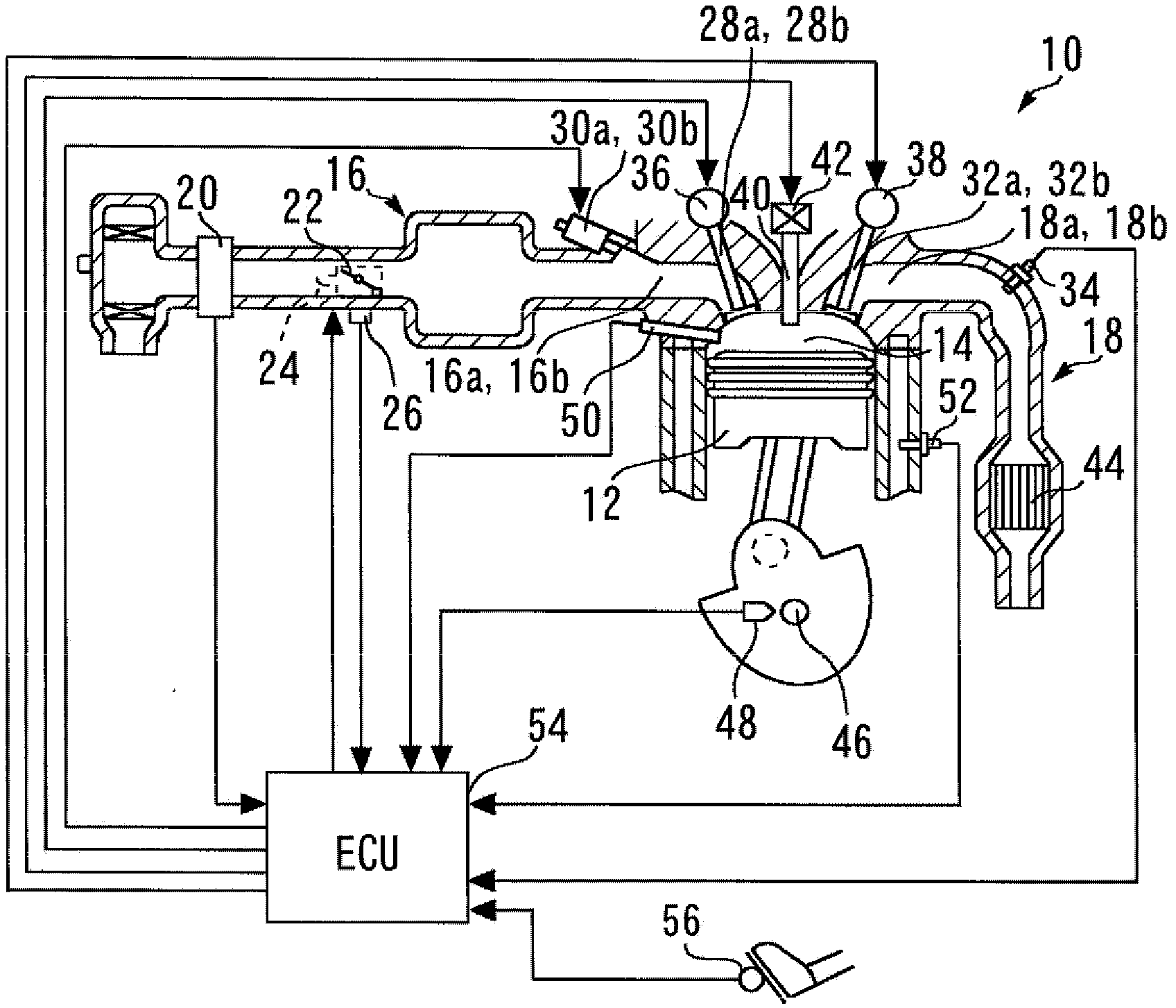
[0053] figure 1 It is a figure for demonstrating the system structure of the internal combustion engine 10 of Embodiment 1 of this invention. The number of cylinders and the arrangement of the cylinders of the internal combustion engine of the present invention are not particularly limited, but as an example, the internal combustion engine 10 of the present embodiment is a tandem four-cylinder engine having four cylinders #1 to #4.
[0054] A piston 12 is provided in each cylinder of the internal combustion engine 10. In each cylinder, a combustion chamber 14 is formed on the top side of the piston 12. The combustion chamber 14 communicates with the intake passage 16 and the exhaust passage 18. An air flow meter 20 is provided near the entrance of the intake passage 16, and the air flow meter 20 outputs a signal corresponding to the flow rate of air sucked into the intake passage 16.
[0055] A throttle valve 22 is provided...
Embodiment approach 2
[0093] Next, refer to Image 6 The second embodiment of the present invention will be described.
[0094] The system of this embodiment can be used figure 1 The hardware structure shown and make ECU54 replace Figure 5 The routine shown is executed later Image 6 The routine shown is implemented.
[0095] The control of the first embodiment described above is also executed in the system of this embodiment. On this basis, in the present embodiment, the first exhaust valve 32a and the second exhaust valve 32b are alternated every predetermined period before obtaining the first and second air-fuel ratios A / F1 and A / F2. Open exhaust valve.
[0096] Image 6 It is a flowchart showing a control routine executed by the ECU 54 in order to realize the control of the second embodiment of the present invention. In addition, in Image 6 Regarding the Figure 5 Steps that are the same as the steps shown are marked with the same reference numerals and their description is omitted or simply descr...
Embodiment approach 3
[0105] Next, refer to Figure 7 The third embodiment of the present invention will be described.
[0106] The system of this embodiment can be used figure 1 The hardware structure shown and make ECU54 replace Image 6 The routine shown is executed later Figure 7 The routine shown is implemented.
[0107] The system of the present embodiment is characterized in that when the control during the warm-up operation of the second embodiment described above is executed during light-load operation, the following control is additionally executed. That is, in this embodiment, when at least one of the first and second air-fuel ratios A / F1 and A / F2 acquired during light-load operation exhibits a value that is leaner with respect to a predetermined determination value, increase and exhibit At least one of the first and second air-fuel ratios A / F1 and A / F2 of this lean value corresponds to the fuel injection amount of at least one of the first and second fuel injection valves 30a and 30b.
[010...
PUM
 Abstract
Description
Claims
Application Information
 - R&D
- Intellectual Property
- Life Sciences
- Materials
- Tech Scout
- Unparalleled Data Quality
- Higher Quality Content
- 60% Fewer Hallucinations
Browse by: Latest US Patents, China's latest patents, Technical Efficacy Thesaurus, Application Domain, Technology Topic, Popular Technical Reports.
© 2025 PatSnap. All rights reserved.Legal|Privacy policy|Modern Slavery Act Transparency Statement|Sitemap|About US| Contact US: help@patsnap.com


