Post-treatment purifier for internal combustion engine particle emission

A technology for purifying device and particulate matter, applied in exhaust device, muffler device, dispersing particle filtration and other directions, can solve the problems of DPF burning, melting, and restricting the popularization and use of DPF, and achieve the effect of low cost and improving filtration efficiency.

Inactive Publication Date: 2014-06-18
北京英泰世纪环境科技有限公司
View PDF7 Cites 17 Cited by
  • Summary
  • Abstract
  • Description
  • Claims
  • Application Information

AI Technical Summary

Problems solved by technology

The filter function of the filter wall cannot be fully exerted after the air inlet at the front end of the DPF is blocked by particulate matter
Under such circumstances, forcibly regenerating, it is likely to cause too much soot to react suddenly on the DPF and release a lot of heat, causing the DPF to be burned or melted
This is the biggest problem in the practical application of DPF, and it is also the biggest obstacle restricting the promotion and use of DPF

Method used


Image

  • Post-treatment purifier for internal combustion engine particle emission
  • Post-treatment purifier for internal combustion engine particle emission
  • Post-treatment purifier for internal combustion engine particle emission

Examples


Embodiment 1

[0045] This example is a sample made by using the device for the post-treatment and purification of the internal combustion engine particulate matter in combination with the front-end DOC, see the brief Figure 5 .

[0046] The engine bench test is used to test the conversion efficiency of particulate matter. The working condition adopts 13 state points from idling speed to rated speed. After stabilization, the concentration of PM in the exhaust gas is measured, and after the collection is completed, it is converted into the total emission of PM. The engine is a domestically produced 1.8L diesel engine.

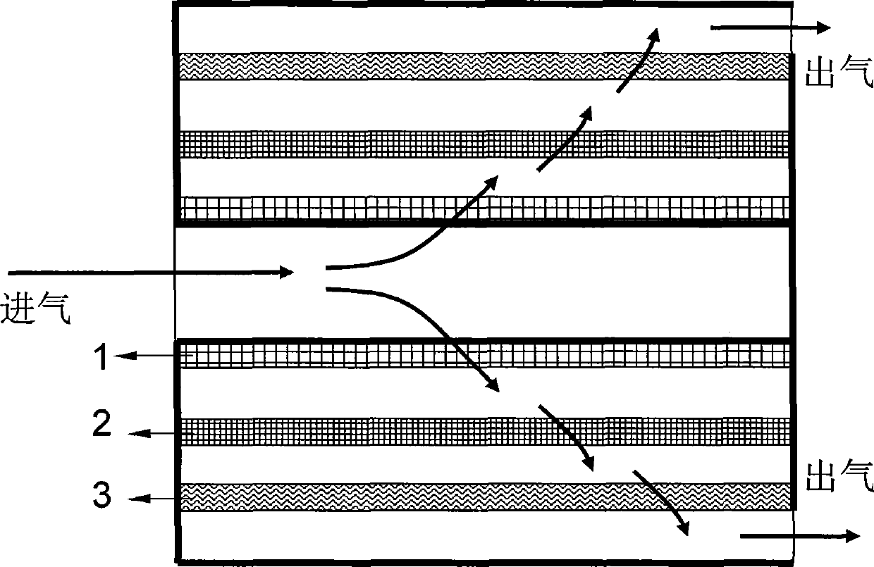
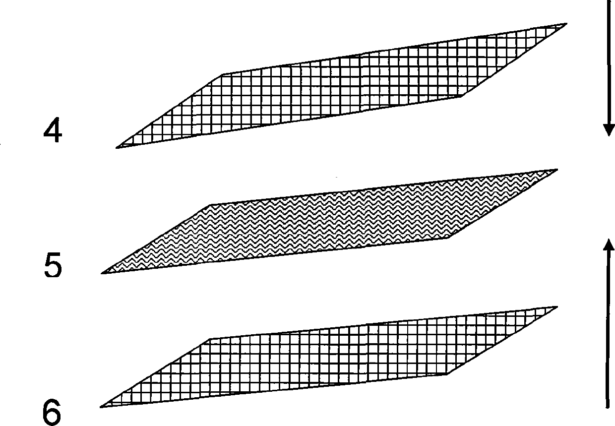
[0047] In order to improve the light-off temperature, the DOC in the front section adopts a 400-mesh 2.0L metal carrier, and the particulate matter purification part in the rear section adopts a 3-layer filter structure. Some use metal mesh panels.

[0048] Pressure sensors are placed before and after the whole device, and all pressure sensors are connected to the pressure ...

Embodiment 2

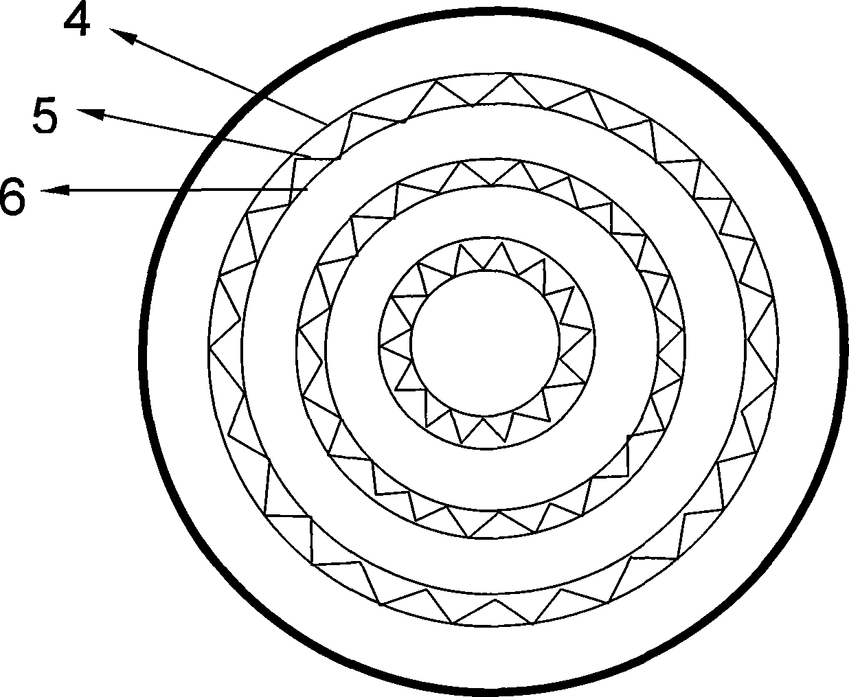
[0054] This example is a sample made by using the device for the post-treatment and purification of the internal combustion engine particulate matter in combination with the front-end DOC, see the brief Image 6 .

[0055] The front section is the same as in Example 1, and the first layer of the particle purification part in the back section adopts a ring-shaped iron-chromium-aluminum wire mesh structure, and the surface is coated with a precious metal catalyst to improve the oxidation ability of large particles and implement passive regeneration. The other two-stage filter body adopts the same structure as that of Example 1 and the iron-chromium-aluminum fiber felt structure.

[0056] The engine is the engine in Example 1. After installing the purification device, the particle emission is 0.021g / kwh, and the conversion efficiency reaches 79%.


PUM

PropertyMeasurementUnit
conversion efficiencyaaaaaaaaaa

Abstract

The invention provides a post-treatment purifier for internal combustion engine particle emission, and belongs to the technical field of environmental protection. The purifier is characterized by employing coercive means of circulation to change the exhaust path, so that all the exhaust passes through the filter; at the same time, the purifier employs filter combination with different trapping efficiencies (material, shape, density), so that smoke or / and particles with different particle sizes are respectively trapped to improve the trapping efficiency; and the purifier solves the problem of the surge of exhaust backpressure caused by rapid accumulation of smoke or / and particle in a trap device for internal combustion engine particle discharge of the prior art. Regeneration of particles can be carried out in any continuous or / and intermittent regeneration mode, such as filter catalyst coating, or be combined with other regeneration mode. The purifier reaches an overall filtration efficiency range as wide as 30-90%, and can be used as post-treatment purifier for a variety of internal combustion engine particle emission. After loading on a diesel engine, the particle emission can reach higher than grade four in national standard.

Description

technical field [0001] The invention relates to a post-treatment and purification device for particulate matter discharged from an internal combustion engine Background technique [0002] Motor vehicles, especially locomotives powered by compression ignition engines (such as diesel engines), contain a large amount of soot and various organic substances in the exhaust gas emitted by them, which will cause great harm to the human body and the environment. harm. The control of soot or particulate matter emission is the focus and hotspot of motor vehicle emission research at present, and it is also a key technical point for upgrading the National III emission standard to the National IV emission standard. The National IV standard requires particulate matter to be reduced by 80% compared with the National III emission standard . At the same time, other industrial boilers and alternative fuel internal combustion engines also have particulate matter emission problems, and there i...

Claims


Application Information

Patent Timeline
Patent Type & Authority Applications(China)
IPC IPC(8): B01D46/24B01D53/86F01N3/035
Inventor 王健潘陆陆
Owner 北京英泰世纪环境科技有限公司
Why Eureka
Try Eureka