
Tail gas treatment method and device for CVD/CVI technique

A tail gas treatment and tail gas technology, which is applied in separation methods, chemical instruments and methods, and the use of liquid separation agents, can solve problems such as difficulty in opening, inability to filter solid and liquid organics, abnormal wear of vacuum pumps, etc., to improve work safety factor and Cost, reduced site occupation area, simple and compact structure

Active Publication Date: 2015-08-12
XIAN XINGUI CERAMIC COMPOSITE MATERIAL CO LTD
View PDF4 Cites 7 Cited by
  • Summary
  • Abstract
  • Description
  • Claims
  • Application Information

AI Technical Summary

Problems solved by technology

Hydrocarbons and tars in the reaction products will liquefy as the temperature of the exhaust gas drops and become highly viscous organic matter, adhering to the inner walls of pipes, valves, vacuum pumps and other devices, affecting the movement and control functions of movable components, resulting in a decrease in the sealing effect of the system
In addition, organic matter with high viscosity will also affect the fluidity of the pump oil, resulting in a decrease in the operating capacity of the vacuum pump rotor, resulting in insufficient suction or difficulty in opening the vacuum pump (pump stuck) and abnormal wear of the vacuum pump, which will affect the normal preparation process.
Therefore, removing viscous organic matter in the previous stage can not only improve the working stability of metal devices, but also save extra labor caused by frequent cleaning of vacuum units. The existing tail gas treatment devices cannot fully treat solid and liquid organic matter. Filtration, and the equipment occupies a large area

Method used


Image

  • Tail gas treatment method and device for CVD/CVI technique
  • Tail gas treatment method and device for CVD/CVI technique

Examples


Embodiment Construction

[0039] Preferred modes of the present invention will be described below with reference to the accompanying drawings.

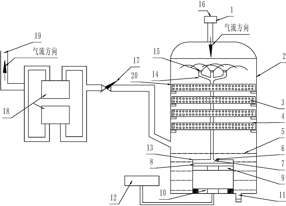
[0040] The present invention is a kind of tail gas adsorption device for CVD / CVI process, comprising the intake pipeline 16, adsorption device, butterfly valve 17, vacuum pump 18 and exhaust pipe 19 connected in sequence, the intake pipeline passes through bellows, flange ring and The bottom of the furnace body of CVD / CVI is connected.

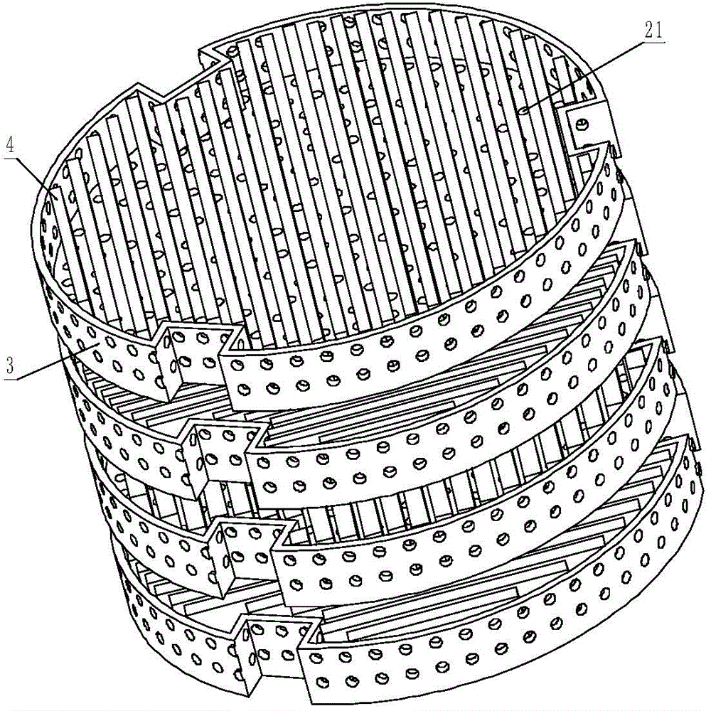
[0041] The adsorption device includes a tank body 2, an organic matter adsorption component arranged in the tank body 2, an oil mist spray component and adsorption oil, the tank body 2 is a metal tank body, and the oil mist spray component includes a power device, a pressure pipeline and multiple A fuel injector, the fuel injector 15 is arranged on the top of the inner cavity of the tank body 2, a plurality of fuel injectors 15 are connected with corresponding pressure pipelines, the pressure pipelines communicate with the ads...


PUM

PropertyMeasurementUnit
Heightaaaaaaaaaa
Wall thicknessaaaaaaaaaa

Abstract

The invention provides a tail gas treatment method and device for a CVD / CVI technique. Three stages of adsorption which are cooperated and supported with each other are designed, wherein during the primary adsorption, by using the reverse contact between adsorption oil and the tail gas, the mixing time of the tail gas and oil mist is prolonged, the temperature of the tail gas is lowered, the liquefied solid-liquid organics are instantaneously bonded with the adsorption oil and together fall down onto a carbon felt in a crucible, thus the tail gas adsorption capability is improved; meanwhile, after the oil mist with the organics falls down onto the carbon felt strip in the stainless crucible, the bonding capability of th carbon felt is enhanced; when passing through the gapes and vent holes among the carbon felts, the tail gas is again filtered through the carbon felt of multiple layers of densities and gradients; and when the tail gas is exhausted out of a metal tank body, the adsorption oil at the bottom of the tank can be used for filtering again. Through the multiple stage filter method, the solid-liquid organics content in the tail gas is greatly reduced, thus the work safety factor and cost of a subsequent metal device are increased.

Description

technical field [0001] The invention relates to the field of tail gas treatment devices, in particular to a tail gas treatment method and equipment for CVD / CVI processes. Background technique [0002] When using chemical vapor deposition / chemical vapor infiltration (referred to as CVD / CVI) to prepare composite materials, tail gas treatment is a difficult problem. Ceramic matrix composite material is a new type of material that replaces metal materials. It has the outstanding advantages of high temperature resistance, corrosion resistance, low density and high strength. It has broad application prospects in aviation, aerospace, weaponry and other fields. In the process of preparing ceramic matrix composites by CVD / CVI, H2, Ar and organosilane are introduced into the furnace, and the tail gas after multi-stage reaction contains undecomposed organosilane, reaction product HCl, decomposition product tar, precipitated product particles, Carrier gas H2 and diluted Ar etc. Hydroc...

Claims


Application Information

Patent Timeline
IPC IPC(8): B01D47/12
Inventor 冯锋左新章成来飞邬国平马玉洁李华民
Owner XIAN XINGUI CERAMIC COMPOSITE MATERIAL CO LTD
Learn More