Mining porous spiral-type foam generating device

A foam generating device and spiral technology, applied in the direction of dissolving, mixing machines, chemical instruments and methods, etc., can solve problems such as difficult to determine energy loss, poor reliability of the overall structure, difficult disassembly and maintenance, etc., to improve reliability, The effect of simple structure and convenient maintenance

Inactive Publication Date: 2014-06-18
CHINA UNIV OF MINING & TECH +1
View PDF4 Cites 28 Cited by
  • Summary
  • Abstract
  • Description
  • Claims
  • Application Information

AI Technical Summary

Problems solved by technology

Such as: the U.S. patent "Air/liquidstaticfoamgenerator" published on February 20, 1996 (application number: US8/2509814, publication number: US054926556), which uses alternate left and right screwers arranged in the cylinder to conduct flow, which is relatively The eddy current loss in the foaming process is greatly reduced and the foaming effect is improved, but its helical structure is an isolated body rather than a continuous part. New eddy current clusters are likely to appear in the foam during the left-right spiral transition process, and the energy loss is difficult to determine ; The Chinese patent "Compressed Gas Foam Fire Extinguishing System Gas-Liquid Proportion Mixing Foamer" published on November 23, 2

Method used


Image

  • Mining porous spiral-type foam generating device
  • Mining porous spiral-type foam generating device
  • Mining porous spiral-type foam generating device

Examples


Embodiment Construction

[0023] The present invention will be further described below in conjunction with accompanying drawing.

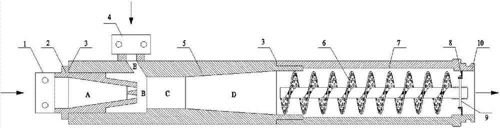
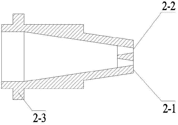
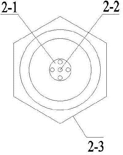
[0024] Such as figure 1 As shown, a mine porous spiral foam generating device of the present invention includes a compressed air joint 1, a nozzle body 2, a gas-liquid mixing chamber 5, a porous spiral foamer 6, a foaming cylinder 7 and a foam outlet joint 10 The outer edge of the front end of the nozzle body 2 is provided with a deck 2-3, and the rear end is provided with at least one outlet nozzle 2-2; the nozzle chamber A in the nozzle body 2 is constricted; The front ends of the nozzle body 2 are connected; the nozzle body 2 is installed inside the front end of the gas-liquid mixing chamber 5; a liquid suction chamber E is opened on the front side wall of the gas-liquid mixing chamber 5; the liquid suction chamber E is installed There is a liquid inlet joint 4; the rear end of the gas-liquid mixing chamber 5 is connected to the front end of the foaming cylinder 7, and ...


PUM

PropertyMeasurementUnit
Apertureaaaaaaaaaa
Pitchaaaaaaaaaa

Abstract

The invention discloses a mining porous spiral-type foam generating device. The mining porous spiral-type foam generating device comprises a compressed air joint (1), a nozzle body (2), a gas-liquid mixing chamber (5), porous spiral-type foamers (6), a foaming cylinder body (7) and a foam outlet joint (10), wherein the rear end of the nozzle body (2) is provided with at least one outlet nozzle; a nozzle cavity in the nozzle body (2) is of a circular truncated cone contracted shape; the compressed air joint is connected with the nozzle body; the nozzle body is installed at the inner side of the front end of the gas-liquid mixing chamber; the porous spiral-type foamers are installed in the foaming cylinder body. A multi-nozzle jet flow structure provided by the invention can achieve low-resistance high-efficiency mixing of a gas phase and a liquid phase. A wire surface high-multiple foaming and spiral low-resistance high-efficiency heat transfer mass transfer coupling mechanism is adopted for foaming, so that the foaming performance of the device is improved greatly; the generated foam is low in wind to foam ratio, is high in foaming quantity and is high in foam forming ratio; the resistance loss in the mixing and foaming process is reduced; the driving pressure of the device is improved; easily damage moving components in a turbulent flow foaming device are discarded; the device foaming reliability is improved.

Description

technical field [0001] The invention relates to a foam generating device, in particular to a mine-used porous spiral foam generating device, which belongs to the field of foam generating devices. Background technique [0002] Foam dust reduction is an important dust reduction technology in high-concentration dust-producing areas of coal mines. Domestic and foreign studies have shown that foam has the advantages of good adhesion, large coverage area, and fast wetting speed in the process of dust treatment, which is incomparable to water mist. , this technology has been applied in mining areas such as the United States, the United Kingdom, the former Soviet Union, and China. However, in the process of foam dust suppression, due to the unreasonable design of the structure of the foam generator, there is a large resistance in the foaming process, low foaming efficiency, and low foaming capacity. Weakness and other defects make its cost rise sharply, which seriously restricts the...

Claims


Application Information

Patent Timeline
IPC IPC(8): B01F13/10
Inventor 王德明陆新晓刘建安沈威曹凯何飞
Owner CHINA UNIV OF MINING & TECH
Why Eureka
Try Eureka