Refining cover for continuous casting tundish and manufacturing method of refining cover

The technology of continuous casting tundish and refining hood is applied in the field of refining hood and its preparation, and can solve the problems of affecting the service life of the tundish hood, low service life of the dipping hood, waste of argon gas resources, etc.

Active Publication Date: 2014-06-18
LAIWU STEEL YINSHAN SECTION CO LTD
View PDF8 Cites 3 Cited by
  • Summary
  • Abstract
  • Description
  • Claims
  • Application Information

AI Technical Summary

Problems solved by technology

However, this invention has the following disadvantages: 1) The cover body (12) of the dipping hood is a single-layer steel plate structure, which is prone to deformation under high temperature conditions and causes the refractory material of the immersed part (13) to fall off, resulting in a low service life of the dipping hood
2) There is an exhaust hole on the cover body of the dipping hood, and the argon blown out from the air-permeable brick air chamber passes through the molten steel gas and is discharged from the exhaust hole on the dipping hood, and the hot and humid argon directly flushes the tundish above the dipping hood The cover is

Method used


Image

  • Refining cover for continuous casting tundish and manufacturing method of refining cover
  • Refining cover for continuous casting tundish and manufacturing method of refining cover
  • Refining cover for continuous casting tundish and manufacturing method of refining cover

Examples


Embodiment 1

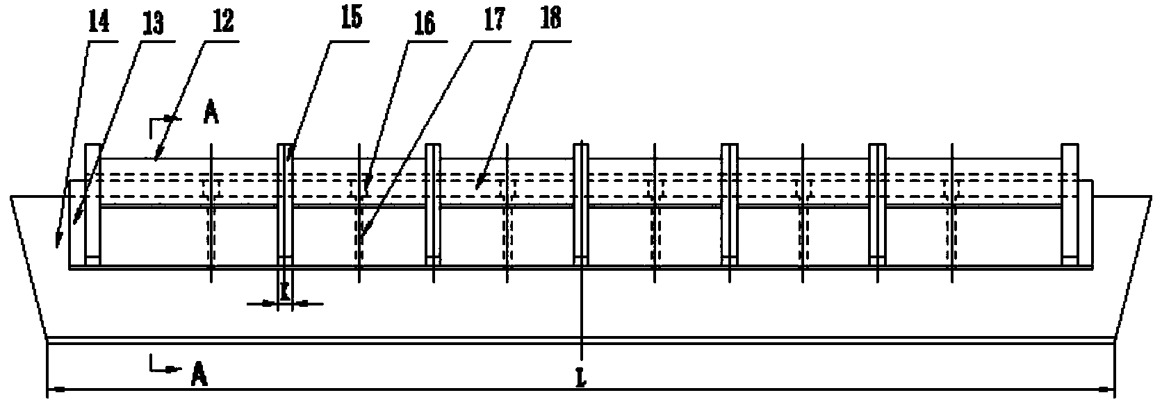
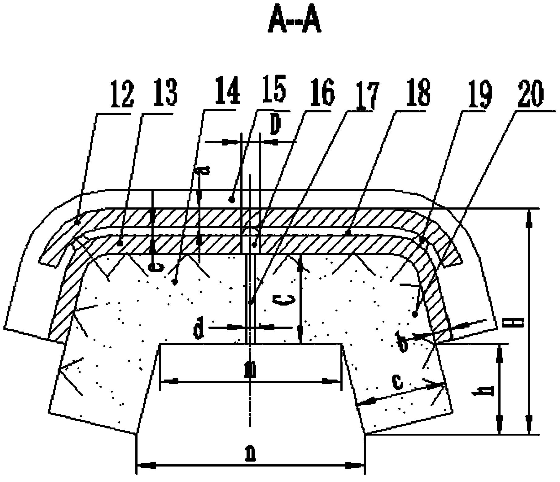
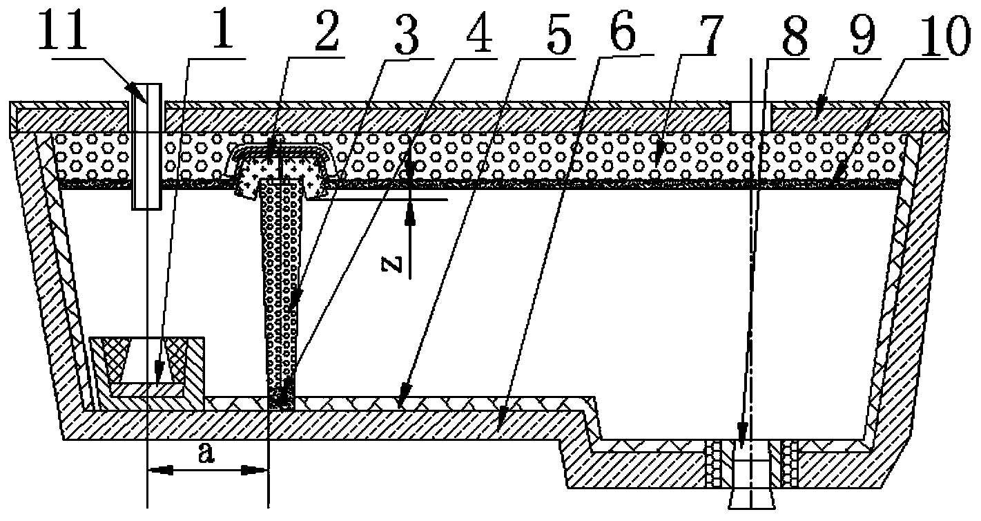
[0049] A refining cover for continuous casting tundish, the structure is as follows figure 1 , figure 2 As shown, it includes an outer arc plate 12, an inner arc plate 13 and an impregnation cover 14. The inner arc plate 12 is set on the impregnation cover 14, and anchor nails 20 are arranged on the inner wall of the inner arc plate 13. The inner arc plate 13 The anchor nail 20 is fixedly connected with the dipping cover 14, the outer arc plate 12 is set above the inner arc plate 13, and a connecting ball 19 is fixed on the outer wall of the inner arc plate 13, and the outer arc plate 12 is connected to the inner arc plate through the connecting ball 19. 13 are connected together, and there is a gap between the outer arc plate 12 and the inner arc plate 13, the gap is a circulation joint 18, the height e of the circulation joint 18 is 10mm, and the circulation joint 18 is connected with the tundish cover 9 and the steel slag layer in the tundish The gaps between 10 are conne...

Embodiment 2

[0054] The preparation method of the refining cover for continuous casting tundish described in embodiment 1 comprises the following steps:

[0055] 1) Process the outer arc plate 12, the inner arc plate 13, and the rib plate 15 respectively, and weld the anchor nail 20 on the inner cavity wall of the inner arc plate 13;

[0056] 2) Place the inner arc plate 13 on the vibrating table of the prefabricated part, support the pouring tire mold with the dipping cover, and apply lubricating oil on the inner wall of the pouring tire mold with the dipping cover;

[0057] 3) After weighing the composition materials of the corundum-spinel castable used for the impregnation cover 14, add them to the mixer for dry mixing for 2 minutes, add 5.0% water of the total weight of the materials, and wet mix for 4 minutes, mix;

[0058] 4) Put the mixed pouring material into the tire mold, and vibrate with a vibrating rod while feeding until the surface is flooded and completely exhausted, then s...

Embodiment 3

[0062] The refining cover for continuous casting tundish as described in embodiment 1, the difference is:

[0063] The height e of the circulation slot 18 is 20 mm, the number of through holes 16 on the inner arc plate 13 is 9, the inner diameter D of the through holes 16 is 25 mm, the number of exhaust holes 17 on the dipping cover 14 is 9, and the inner diameter of the exhaust holes 17 is d 15mm.

[0064] The cross-section of the dipping hood is trapezoidal. Inside the trapezoid, there is an inner cavity with an open bottom. The inner cavity is a trapezoid with a narrow top and a wide bottom. The upper width m of the inner cavity is 250mm, and the bottom width n is 350mm. The thickness c of 14 is 100mm. The outer arc plate 12 and the inner arc plate 13 have the same thickness, and the thickness b of the outer arc plate 12 and the inner arc plate 13 is 25mm, both including the horizontal plate and the side plate, the horizontal plate is arranged horizontally and parallel to ...


PUM

PropertyMeasurementUnit
Thicknessaaaaaaaaaa
Top widthaaaaaaaaaa
Bottom widthaaaaaaaaaa

Abstract

The invention relates to a refining cover for a continuous casting tundish and a manufacturing method of the refining cover. The refining cover comprises an outer arc plate, an inner arc plate and a dipping cover. A circulation seam is reserved between the outer arc plate and the inner arc plate, and communicated with a gap between a tundish cover and a steel slag layer inside the tundish. Air exhaust holes penetrating through the dipping cover are formed in the dipping cover, through holes opposite to the air exhaust holes are formed in the inner arc plate, the air exhaust holes are communicated with the circulation seam through the through holes, argon is blown in through air curtain ventilation bricks, an air curtain barrier with the large continuous intensity is formed between the air curtain ventilation bricks and the dipping cover, the inclusions are captured and are adsorbed and removed by the steel slag layer, the argon breaks through the steel slag layer below the dipping cover to move upwards continuously and enters the circulation seam through the air exhaust holes and the through holes, the argon enters the position above the steel slag layer of the tundish through the circulation seam, and argon seal is formed in the space between the steel slag layer inside the tundish and the tundish cover. The steel slag face is protected, secondary oxidation of liquid steel is avoided, the 0.5 level of the four kinds of inclusions in LHG2 steel reaches more than 90%, and the cleanliness of the liquid steel is greatly improved.

Description

technical field [0001] The invention relates to a refining cover for a continuous casting tundish and a preparation method thereof, belonging to the technical field of iron and steel metallurgy continuous casting tundish technology. Background technique [0002] Continuous casting tundish air curtain retaining wall technology is a new technology developed at the end of the 20th century to remove non-metallic inclusions in molten steel in continuous casting tundish. Bricks are placed at a certain position at the bottom of the tundish, and argon gas is blown in, and the argon gas floats through the breathable brick to form a micro-bubble air curtain barrier. The purpose of removing inclusions and purifying molten steel. [0003] Although the existing air brick air curtain retaining wall can remove the inclusions in the molten steel to a certain extent and serve the purpose of purifying the molten steel, it still has the following technical defects. Large blowing volume will ...

Claims


Application Information

Patent Timeline
IPC IPC(8): B22D11/117
Inventor 武光君毛鲁波
Owner LAIWU STEEL YINSHAN SECTION CO LTD
Why Eureka
Try Eureka