Injection mold automatically-disassembling device
A technology for injection molds and dismantling devices, which is applied in the direction of manufacturing tools, metal processing equipment, metal processing, etc., can solve the problems of high labor intensity in operation, unfavorable batch assembly line operations, and waste of human resources, so as to reduce labor intensity and labor costs , Conducive to batch assembly line operations, to achieve the effect of safe production
- Summary
- Abstract
- Description
- Claims
- Application Information
AI Technical Summary
Problems solved by technology
Method used
Image
Examples
Embodiment 1
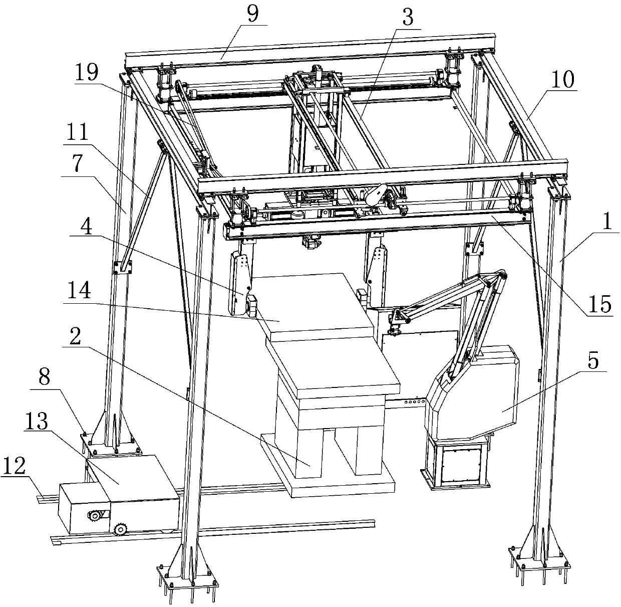
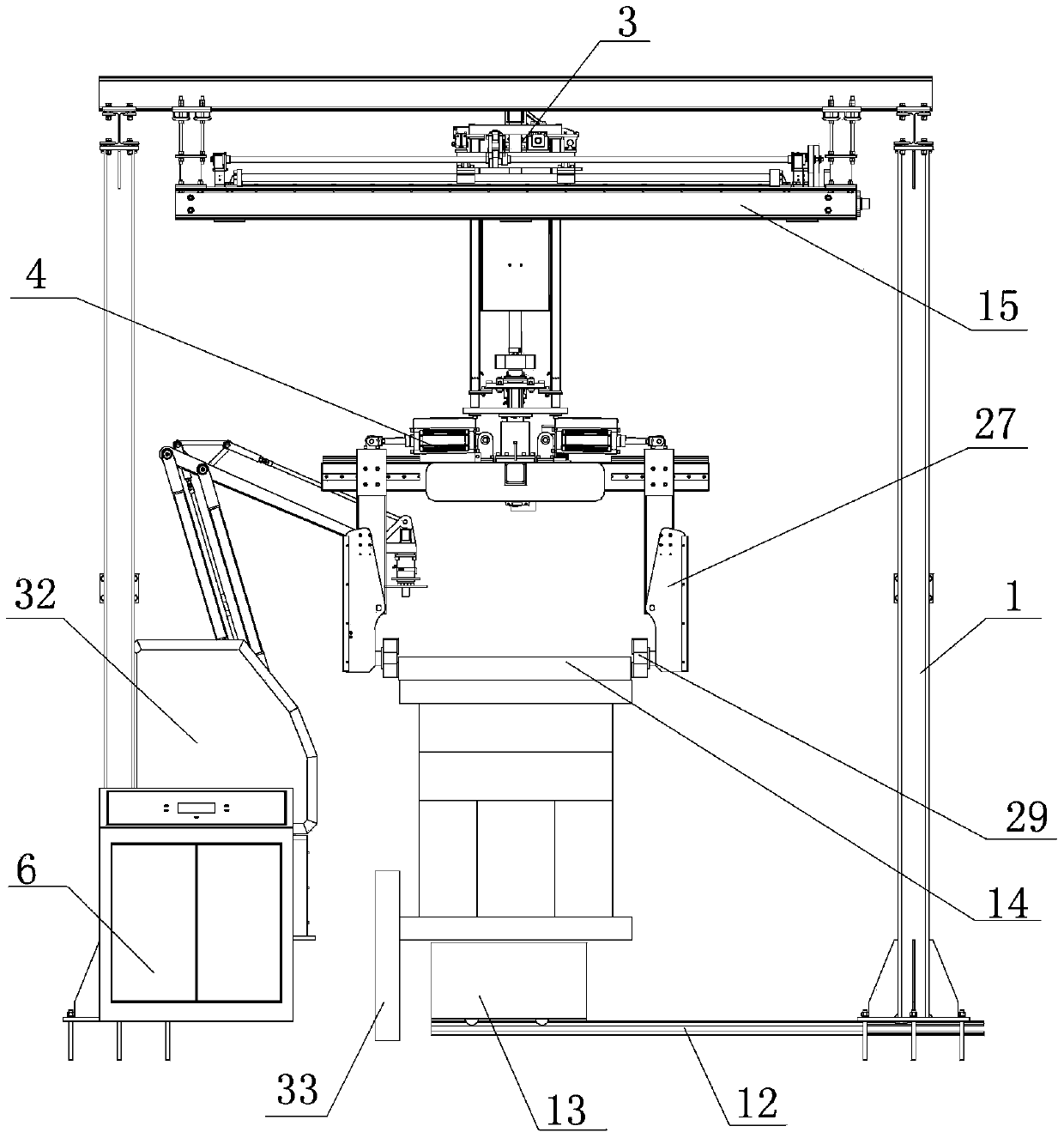
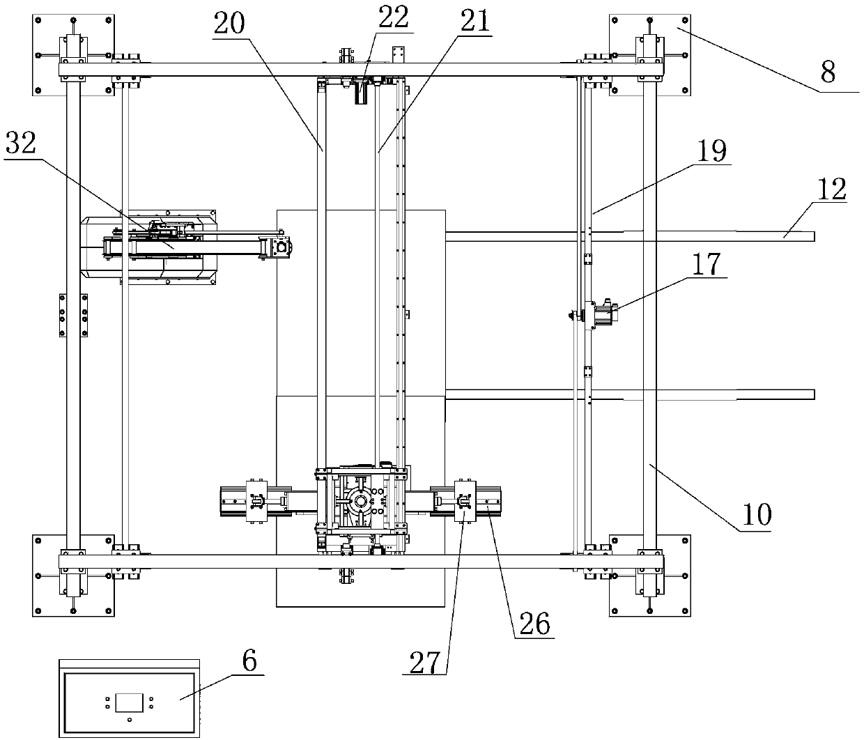
[0030] Such as Figure 1 to Figure 3 As shown, an automatic dismantling device for an injection mold according to the present invention includes a gantry 1, a workbench for carrying the mold 2, and a walking mechanism for driving the mold 2 to travel in the three directions of X, Y, and Z axes. 3. A clamping and turning mechanism 4 for clamping and turning over the mold 2 , a dismantling mechanism 5 and a control cabinet 6 for disassembling the mold 2 .
[0031] The running mechanism 3 is installed on the gantry 1, and the clamping and turning mechanism 4 is installed on the running mechanism 3. The running mechanism 3, the clamping and turning mechanism 4 and the dismantling mechanism 5 are all connected with the control cabinet 6, and are controlled by the control cabinet 6. The control cabinet 6 is installed on one side of the gantry 1, and is not placed inside the gantry 1, so as to avoid potential safety hazards caused by personnel entering and leaving the gantry 1.
[0...
Embodiment 2
[0053] Such as Figure 7 As shown, the difference from Embodiment 1 is that a positioner 34 is installed inside the gantry 1,
[0054] The mold 2 is transported to the inside of the gantry 1 by the ground rail trolley 13, and automatically transferred to the positioner 34. The positioner 34 can drive the mold 2 to rotate 360° on the horizontal plane, which is more conducive to adjusting the processing position of the mold 2. Easy to hold, flip and transport. The positioner 34 is connected with the control cabinet 6 and controlled by the control cabinet 6 .
Embodiment 3
[0056] Such as Figure 8 , Figure 9 and Figure 10 As shown, the clamping hands 29 are C-shaped, each clamping hand 29 is connected with a hydraulic mechanism 38, the hydraulic mechanism 38 is connected with the control cabinet 6, a polyurethane gasket 39 is fixed at the end of the telescopic rod of the hydraulic mechanism 38, and the clamping hand 29 is inserted into the edge of the formwork 14 from both sides, and the action of the hydraulic mechanism 38 is controlled, and the telescopic rod is stretched out to push the polyurethane gasket 39 to compress the formwork 14, thereby clamping the formwork 14.
[0057] Because the template 14 is attached more closely layer by layer, in order to facilitate the clamping hand 29 to clamp the template 14, a magnetic adsorption device 40 is arranged above the mold 2 in the middle of the two clamp arms 27, and the magnetic adsorption device 40 is used for from Adsorb the mold 2 above, so that the mold 2 can be lifted up about 10cm, w...
PUM
 Abstract
Description
Claims
Application Information
 - R&D
- Intellectual Property
- Life Sciences
- Materials
- Tech Scout
- Unparalleled Data Quality
- Higher Quality Content
- 60% Fewer Hallucinations
Browse by: Latest US Patents, China's latest patents, Technical Efficacy Thesaurus, Application Domain, Technology Topic, Popular Technical Reports.
© 2025 PatSnap. All rights reserved.Legal|Privacy policy|Modern Slavery Act Transparency Statement|Sitemap|About US| Contact US: help@patsnap.com


