Sleeve grooving machine and sleeve grooving method thereof
A slotting machine and sleeve technology, which is applied to the parts of grinding machine tools, grinding machines, grinding/polishing equipment, etc. The effect of reducing the labor intensity of workers, reducing the number of operating workers, and improving production efficiency
- Summary
- Abstract
- Description
- Claims
- Application Information
AI Technical Summary
Problems solved by technology
Method used
Image

Examples
Embodiment 1
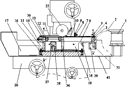
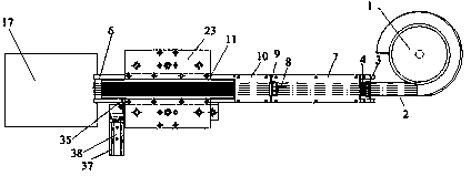
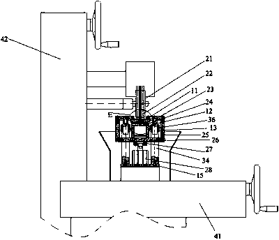
[0048] see Figure 1 to Figure 7 , the sleeve slotting machine includes a cutting machine tool main body 20, a cutting support frame body, a feeding mechanism, a conveyor belt driving mechanism, a conveyor belt 6, a feeding material distribution mechanism and a sleeve fixing mechanism, such as image 3 As shown, the main body 20 of the cutting machine tool includes a bed, a grinding wheel support arranged in the Z-axis direction of the bed (ie, the longitudinal / vertical direction), a Z-axis slide 42, horizontal direction), the Z-axis sliding table drive mechanism for moving the Z-axis sliding table 42 up and down along the Z-axis direction of the bed, and the worktable for moving the worktable 41 left and right along the X-axis direction of the bed Drive mechanism, the workbench is an X-axis slide table, the grinding wheel support is installed on the Z-axis slide table 42, and the grinding wheel support is provided with several grinding wheels 22 and a grinding wheel drive mec...
Embodiment 2
[0079]This embodiment has the same features as Embodiment 1 except for the following features: the sleeve fixing mechanism includes a clamping plate, a supporting plate for supporting the sleeve to be processed, and a support plate connected with the clamping plate and used to control the lifting of the clamping plate Pressing lifting mechanism, the pressing lifting mechanism is connected with the cutting support frame; the pressing plate is arranged below the grinding wheel and above the conveyor belt; The material plates are parallel; cutting slots corresponding to the grinding wheel and parallel to the workbench are provided on the pressure material plate.
[0080] A pressure groove matching the sleeve to be processed is provided on the pallet, and the pallet is covered and connected above the conveyor belt.
[0081] The cross section of the pressing groove is V-shaped.
[0082] The pressing groove on the supporting plate is connected with the material channel on the mater...
PUM
 Abstract
Description
Claims
Application Information
 - R&D
- Intellectual Property
- Life Sciences
- Materials
- Tech Scout
- Unparalleled Data Quality
- Higher Quality Content
- 60% Fewer Hallucinations
Browse by: Latest US Patents, China's latest patents, Technical Efficacy Thesaurus, Application Domain, Technology Topic, Popular Technical Reports.
© 2025 PatSnap. All rights reserved.Legal|Privacy policy|Modern Slavery Act Transparency Statement|Sitemap|About US| Contact US: help@patsnap.com