Drive axle for mobile working machine

A technology for driving axles and working machines, which is applied in the direction of motor vehicles, connected with control/drive circuits, and combined cooling of power plants, etc., which can solve the problems of expansion of cooler devices, cost of laying pipes, cost of laying hoses, etc. problems, to achieve the effect of reducing structural costs

Active Publication Date: 2014-06-18
LINDE MATERIAL HANDLING
View PDF11 Cites 9 Cited by
  • Summary
  • Abstract
  • Description
  • Claims
  • Application Information

AI Technical Summary

Problems solved by technology

Especially in working machines designed as floor conveyors, installation space problems arise in this case, which can only achieve the required enlargement of the cooler arrangement of the working hydraulics with increased structural outlay.
Furthermore, the coupling of the liquid-cooled drive axle to the operating hydraulics of the working machine entails additional piping and hose laying costs

Method used


Image

  • Drive axle for mobile working machine

Examples


Embodiment Construction

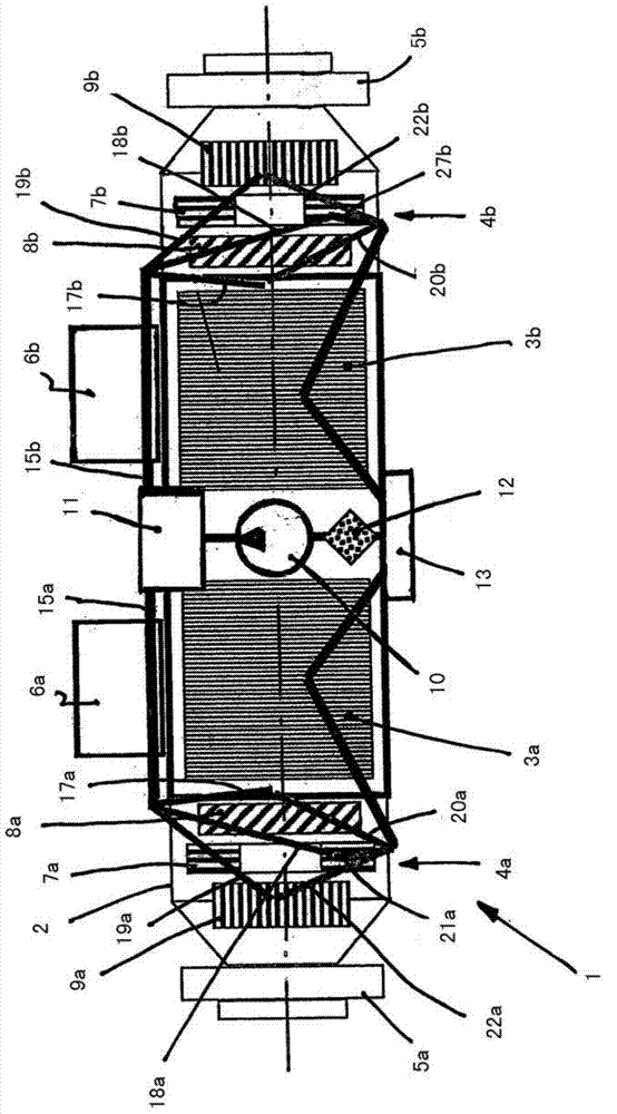
[0024] The drive axle 1 according to the invention is preferably designed as a dual-motor axle, wherein two electric traction motors 3 a , 3 b in the form of asynchronous motors are arranged in an axle housing 2 , which are each coupled to a transmission 4 a in between. In the case of , 4b, the drive hubs 5a, 5b are used to receive and fix a drive wheel not shown in each case. For controlling each electric traction motor 3a, 3b, an electric power electronics device 6a, 6b, for example a commutator, is provided, which are fastened directly to the axle housing 2 and are thus flanged to the drive axle 1 on.

[0025] In the exemplary embodiment shown, the transmissions 4a, 4b are designed as double-reduction transmissions with a braking device 7a, 7b. In the exemplary embodiment shown, the braking devices 7a, 7b are arranged between an inlet stage 8a, 8b and an outlet stage 9a, 9b of the transmission 4a, 4b, which are driven by the corresponding travel motor 3a, 3b drive, said out...


PUM


Abstract

The invention relates to a drive axle (1) for a mobile working machine, especially for a ground conveying machine. The drive axle at least comprises electric drive motors (3a; 3b), power electronic devices (6a; 6b) manipulating the drive motors (3a; 3b), and speed changers (4a; 4b) driven by the drive motors (3a; 3b). The speed changers drive hubs (5a; 5b). A liquid cooling device which is used for the drive motors (3a; 3b), the power electronic device (6a; 6b) and the speed changers (4a; 4b) is equipped with a liquid loop. One or more following parts, a circulating pump (10), a heat exchanger device (11) and a filter (12), of the liquid loop are assembled or attached onto the drive axle (1).

Description

technical field [0001] The invention relates to a drive axle for a mobile working machine, in particular a floor conveyor, which has at least an electric traction motor, a power electronics system for actuating the traction motor and A transmission driven by the travel motor, which drives a hub, wherein the liquid cooling for the travel motor, the power electronics and the transmission is provided with a liquid circuit. Background technique [0002] A generic electric drive axle of a working machine is known from DE 10 2005 037 726 A1. In the drive axle known from this document, the electric traction motor, the transmission downstream of the traction motor and the power electronics controlling the traction motor are liquid-cooled, wherein the liquid-cooled liquid circuit Coupled to working hydraulics of the working machine. Since in this case the working hydraulic pump of the working machine provides the liquid flow for cooling the drive axle, the working hydraulic pump ha...

Claims


Application Information

Patent Timeline
Patent Type & Authority Applications(China)
IPC IPC(8): B60K1/00B60K11/02
CPCB60K17/043B60K2001/006F16H57/04F16H57/0476F16H57/0457H02K7/116H02K9/19B60K2001/003B60K1/00B60Y2200/62F16H57/0412F16H57/0486F16H57/0409B60K7/0007H02K9/26H02K11/33B60K11/02
Inventor S·莱纳V·施赖伯
Owner LINDE MATERIAL HANDLING
Why Eureka
Try Eureka