Autonomous quadrotor unmanned aerial vehicle positioning and controlling method based on laser radar

A four-rotor unmanned aerial vehicle and lidar technology, which is applied in the research field of autonomous flight control of four-rotor unmanned aerial vehicles, can solve the problems of difficult and precise positioning, weak environmental dependence of positioning accuracy, etc.

Active Publication Date: 2014-06-18
TIANJIN UNIV
View PDF5 Cites 63 Cited by
  • Summary
  • Abstract
  • Description
  • Claims
  • Application Information

AI Technical Summary

Problems solved by technology

[0003] The electronic system of the quadrotor drone can be composed of two subsystems, the sensor and the flight control; the sensor system needs to accurately measure or estimate the status of the drone, and it transmits the flight status of the drone to the flight control system, such as position, speed, attitude angle, and angular velocity The control subsystem is used to achieve good flight control; the sensor system can be subdivided into attitude sensors and position sensors; the commonly used attitude sensors are composed of three-axis accelerometers, three-axis gyroscopes, magnetometers and other MEMS components. It can be used both indoors and outdoors; position sensors mostly use GPS, Beidou and other satellite positioning and navigation systems, but it is difficult for this type of sensor to achieve accurate positioning between buildings and indoor environments with weak GPS signals; in order to solve the problem of accurate positioning in the

Method used


Image

  • Autonomous quadrotor unmanned aerial vehicle positioning and controlling method based on laser radar
  • Autonomous quadrotor unmanned aerial vehicle positioning and controlling method based on laser radar
  • Autonomous quadrotor unmanned aerial vehicle positioning and controlling method based on laser radar

Examples


Embodiment Construction

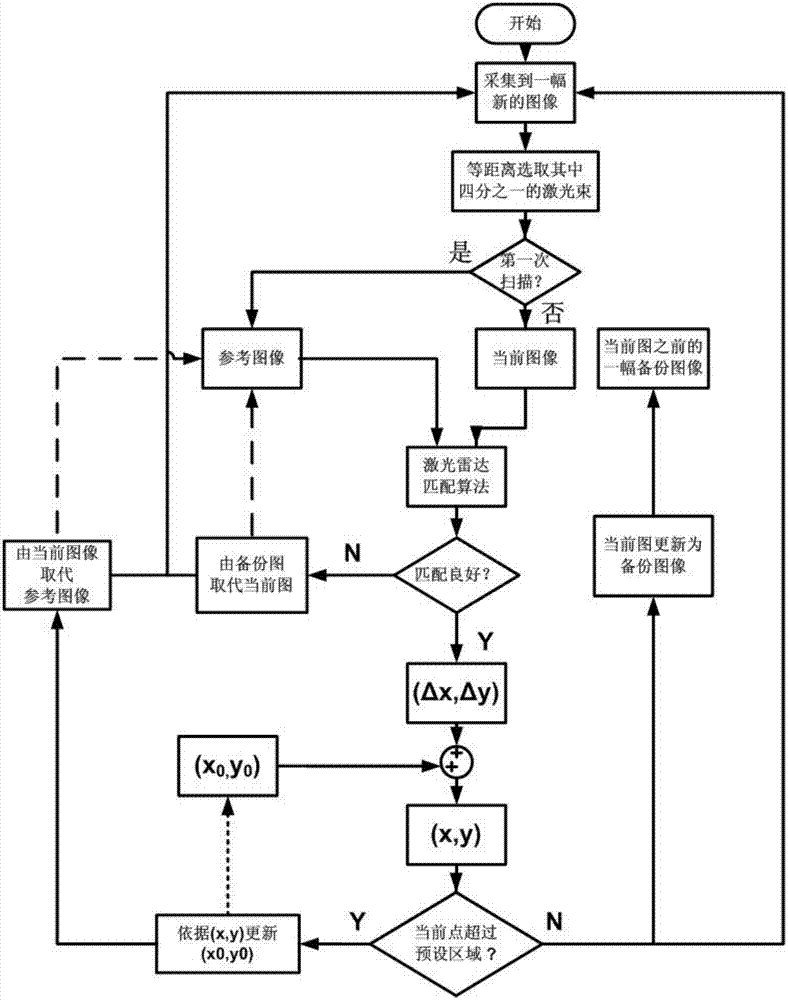
[0048] The technical solution adopted by the present invention is the autonomous positioning and control method of the four-rotor UAV, and the plane displacement and rotation angle measurement: the laser radar is used for iterative relative positioning, so two images need to be selected for comparison, and p is defined here i For a point in the current image, define is a point in the reference image, and the transformation relationship from the reference image to the current image is defined as rotation R(θ) and translation t;

[0049] Assuming that the current number of iterations is k and k>0, iterate until it converges or falls into an iterative loop, and each iterative step is described as follows:

[0050] The first step is to set the initial value of the iteration: if it enters the iterative program for the first time, it will transform and guess the initial value q 0 =(t 0 ,θ 0 ), using the airborne inertial navigation element, by measuring the yaw angle difference ...


PUM


Abstract

The invention belongs to the technical field of autonomous flight control research on a quadrotor unmanned aerial vehicle, and discloses an autonomous positioning method based on a two-dimensional laser radar as well as a design method for a quadrotor unmanned aerial vehicle control system based on the positioning method and other onboard MEMS (micro electro mechanical systems) chips. According to the technical scheme adopted by the invention, the autonomous quadrotor unmanned aerial vehicle positioning and controlling method based on the laser radar comprises the following steps: preliminarily positioning the unmanned aerial vehicle in the horizontal direction by utilizing the two-dimensional laser radar, and acquiring a preliminary position value of the unmanned aerial vehicle in the height direction by utilizing an onboard barometer; then acquiring the position information of the unmanned aerial vehicle with high frequency by combining with onboard accelerometer chips by utilizing a complementary filtering algorithm; and finally, applying to unmanned aerial vehicle control systems without GPS signals based on the position information. The autonomous quadrotor unmanned aerial vehicle positioning and controlling method based on the laser radar, which is provided by the invention, is mainly applied to design and manufacturing of autonomous flight control devices of the unmanned aerial vehicle.

Description

technical field [0001] The invention belongs to the technical field of autonomous flight control research of quadrotor UAVs, and specifically relates to autonomous positioning and control methods of quadrotor UAVs; Background technique [0002] Unmanned aircraft, referred to as unmanned aerial vehicle, is an unmanned aircraft that uses radio remote control or its own program control. Compared with manned aircraft, unmanned aircraft has the advantages of small size, low cost, and convenient use; according to Due to the difference in its structural design, UAVs can be divided into two types: fixed-wing and rotary-wing; quadrotor UAV is a kind of rotary-wing UAV, which has the advantages of small size, simple structure, high safety, and good control over the flying space. The advantages of low requirements have broad application prospects in military and civilian fields, including practical applications such as terrain surveying and mapping, power grid maintenance, air transpor...

Claims


Application Information

Patent Timeline
IPC IPC(8): G01C23/00G05D1/10
CPCG01C5/06G01C21/165G01S17/06G05D1/102
Inventor 鲜斌张垚茹滨超宋英麟
Owner TIANJIN UNIV
Why Eureka
Try Eureka