Wide-beam ion source device used for ion implanter

An ion implanter and ion source technology, applied in the direction of discharge tubes, electrical components, circuits, etc., can solve the problems of wide ion beams and inability to produce them, and achieve the effects of strong beam intensity, uniformity improvement, and enlarged arc chamber size

Inactive Publication Date: 2014-06-18
BEIJING ZHONGKEXIN ELECTRONICS EQUIP
View PDF5 Cites 12 Cited by
  • Summary
  • Abstract
  • Description
  • Claims
  • Application Information

AI Technical Summary

Problems solved by technology

[0003] The purpose of the present invention is to provide a wide-beam ion source device for ion implanters to solve the problem that the wide-beam ion source device in the prior art cannot produce wider ion beams. When the target implanted silicon wafer has a larger width, A complex optical path structure is required to expand the width of the beam and correct the angle to complete the ion implantation problem

Method used


Image

  • Wide-beam ion source device used for ion implanter
  • Wide-beam ion source device used for ion implanter
  • Wide-beam ion source device used for ion implanter

Examples


Embodiment 1

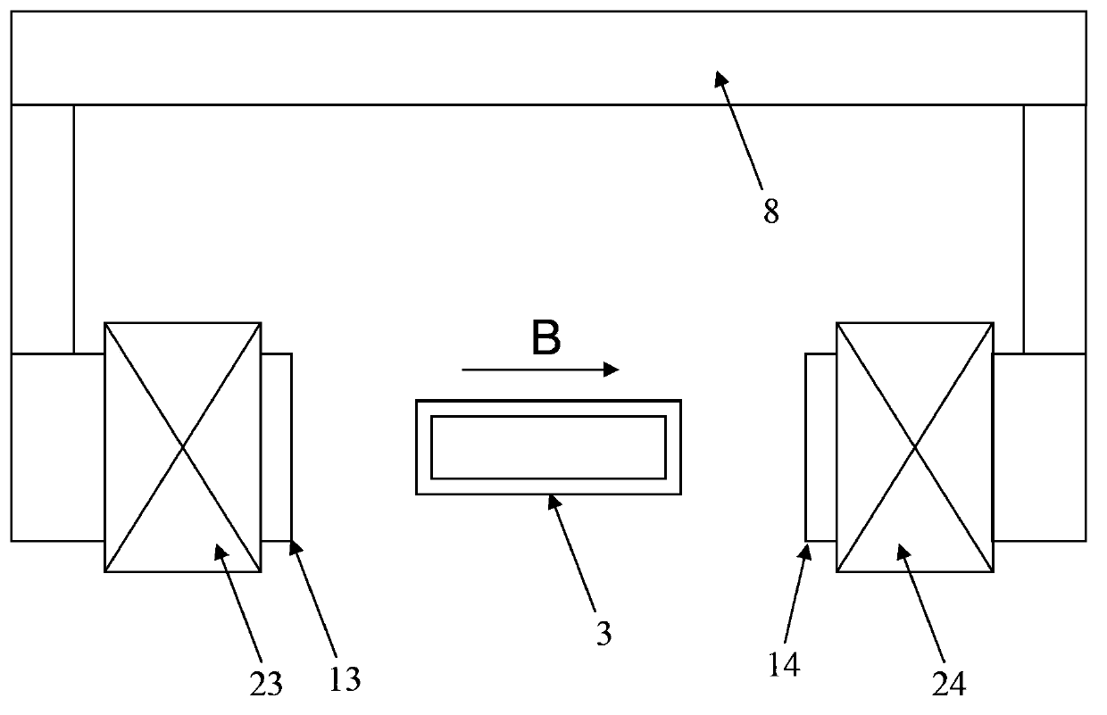
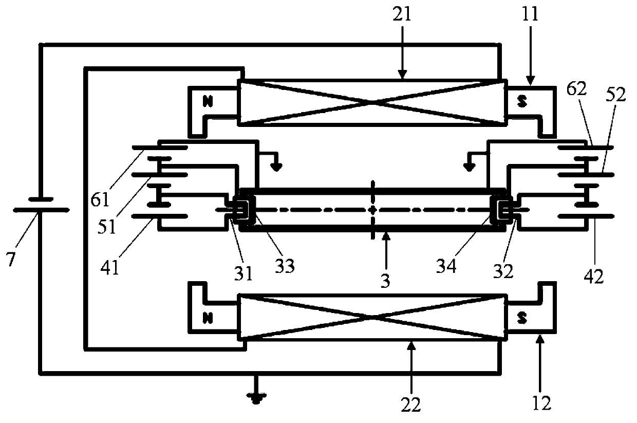
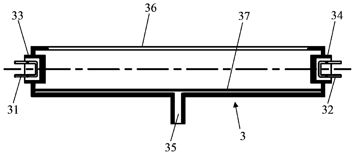
[0042] Such as Figure 2 to Figure 5 As shown, the wide-beam ion source device for an ion implanter in Embodiment 1 includes a source magnetic field iron core, a source magnetic field coil wound on the source magnetic field iron core, an arc chamber 3 and an extraction electrode 9, and the bottom of the arc chamber 3 is provided with There is an air supply hole 35, the top of the arc chamber 3 is provided with a lead-out slit 36, and the lead-out electrode 9 is arranged outside the lead-out slit 36, one end of the arc chamber 3 is provided with a first filament 31 and a first cathode 33, and the other end of the arc chamber 3 is provided with There is a second filament 32 and a second cathode 34, the first filament 31 and the second filament 32 are respectively connected to the filament power supply, the first bias power supply 51 is connected between the first filament 31 and the first cathode 33, the second filament 32 and the second The second bias power supply 52 is connec...

Embodiment 2

[0063] Such as Image 6 As shown, the difference between the wide-beam ion source device of Embodiment 2 and the wide-beam ion source device of Embodiment 1 is only that the source magnetic field coil is different, and the rest of the structures are the same. Only the differences will be described in detail below.

[0064] In order to improve the distribution of the source magnetic field, the source magnetic field with a multi-coil structure is adopted in the second embodiment. By adjusting the driving current of each coil, the uniform distribution state of the source magnetic field in the arc chamber 3 section can be further adjusted to improve the uniformity of the broadband beam current. sex distribution.

[0065] The source magnetic field iron core includes an upper iron core 11 and a lower iron core 12, the upper iron core 11 and the lower iron core 12 are arranged on both sides of the arc chamber 3, and the upper iron core 11 and the lower iron core 12 are along the len...


PUM


Abstract

The invention discloses a wide-beam ion source device used for an ion implanter. The device comprises a source magnetic field iron core, a source magnetic field coil, an arc chamber and an extraction electrode, one end of the arc chamber is provided with a first filament and a first cathode, the other end of the arc chamber is provided with a second filament and a second cathode, the first filament and the second filament are connected with filament power supplies respectively, a first bias power supply is connected between the first filament and the first cathode, a second bias power supply is connected between the second filament and the second cathode, a first arc voltage power supply is connected between the first cathode and the arc chamber, and a second arc voltage power supply is connected between the second cathode and the arc chamber. Since the arc chamber adopts an indirect-heating type double-cathode structure with double filaments and double cathodes, so that a gas medium and hot electrons emitted by the cathodes fully collide, and a relatively wide ion beam and relatively high beam intensity can be generated, thereby facilitating increase of the width of the ion beam, and directly obtaining a parallel wide-band beam that covers the width of a target implantation silicon wafer.

Description

technical field [0001] The invention relates to the technical field of ion implanters, in particular to a wide-beam ion source device for ion implanters. Background technique [0002] Broad-beam ion source device is the core component of ion implanter, which is used to generate broadband ion beam. Such as figure 1 As shown, the wide-beam ion source device in the prior art includes a source magnetic field iron core, a source magnetic field coil wound on the source magnetic field iron core, an arc chamber 3 and an extraction electrode, and the bottom of the arc chamber 3 is provided with an air supply hole, The top of the arc chamber 3 is provided with a lead-out slot, and the lead-out electrode is arranged outside the lead-out slot. Among them, the arc chamber 3 adopts an indirect heated cathode structure with a single filament, a single cathode plus a reflector, the source magnetic field iron core includes a left iron core 13 and a right iron core 14 arranged at both ends ...

Claims


Application Information

Patent Timeline
Patent Type & Authority Applications(China)
IPC IPC(8): H01J37/08H01J37/317
Inventor 彭立波
Owner BEIJING ZHONGKEXIN ELECTRONICS EQUIP
Why Eureka
Try Eureka