Arsenic removal method based on surface in-situ iron plating technology

An iron-plating and technical technology, applied in chemical instruments and methods, adsorption water/sewage treatment, water/sewage treatment, etc., can solve problems such as difficulty in engineering practice and application promotion, wide distribution of arsenic and groundwater, and difficulty in identification. , to achieve the effect of cheap treatment method, intact crystal form and dense structure

Inactive Publication Date: 2014-06-25
CHINA UNIV OF GEOSCIENCES (WUHAN)
View PDF4 Cites 2 Cited by
  • Summary
  • Abstract
  • Description
  • Claims
  • Application Information

AI Technical Summary

Problems solved by technology

However, due to the characteristics of wide distribution, large volume, and difficulty in identifying pollution sources and pollution pathways in naturally occurring high-arsenic groundwater, it is difficult to realize engineering practice and application promotion by both electrochemical methods and in-well aeration methods.

Method used


Image

  • Arsenic removal method based on surface in-situ iron plating technology

Examples


Embodiment 1

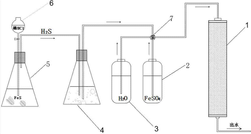
[0019] The arsenic removal device used in this example is as figure 1 As shown, firstly, the cleaned 50-mesh quartz sand and viscous minerals are mixed evenly according to the mass ratio of 9:1, and then filled in a plexiglass column, and the porosity and permeability coefficient of the mixture in the plexiglass column are measured. The inner diameter of the column is 1.4 cm, the height is 30 cm, and the top and bottom of the plexiglass column are respectively provided with a water inlet and a water outlet.

[0020] Then the FeS solid was ground to 100 mesh, mixed with oxygen-free deionized water at a mass ratio of 1:10, configured into a suspension and transferred to H 2 S is generated in the Erlenmeyer flask and sealed with a rubber cork; then configure a dilute hydrochloric acid solution with a mass concentration of 5%, transfer it to a separatory funnel, and then connect the separatory funnel to H 2 S generates Erlenmeyer connection, through to H 2 S is formed by adding ...

Embodiment 2

[0024] In this embodiment, firstly, the washed 50-mesh quartz sand and viscous minerals are mixed evenly according to the mass ratio of 8:2, and the rest of the steps are the same as in Example 1. After the iron plating is completed, the porosity change rate before and after the iron plating is tested. <1%, under the condition of constant water head, the change of permeability coefficient before and after iron plating is <3%. Inject the prepared mixed solution of 500 μg / L Na3AsO4 and Na3AsO3 (1:1 mix) and 5 mg / L NaCl solution into the plexiglass column with a multi-channel peristaltic pump at 3.5 void volume / h. The content of arsenic in the effluent was lower than the detection limit of the atomic fluorescence spectrometer (0.1 μg / L), so the removal rate was greater than 99.99%.


PUM

PropertyMeasurementUnit
The inside diameter ofaaaaaaaaaa
Heightaaaaaaaaaa

Abstract

The invention provides an arsenic removal method based on a surface in-situ iron plating technology. The method comprises the following steps: evenly mixing cleaned silica sand with a viscous mineral, and then filling an organic glass column with a mixture; determining the porosity and the permeability coefficient of a mixture in the organic glass column, wherein a water inlet and a water outlet are respectively formed in the top and the bottom of the organic glass column; introducing an H2S gas into deionized water, so as to prepare a saturated HS- solution; injecting a FeSO4 solution into the organic glass column, and then injecting the deionized water; then injecting the saturated HS- solution into the organic glass column, and circulating the steps until the surface of the mineral is evenly plated. The removal rate of an arsenic element is greater than 99.99%. The defects in the background art are solved, and the method not only is high in arsenic removal efficiency, economical and applicable, free of secondary pollution, strong in feasibility and the like, but also can carry out in-situ plating arsenic removal on an aquifer, and is applicable to engineering practice, and popularization and application.

Description

technical field [0001] The invention provides a method for removing arsenic, in particular relates to a method for removing arsenic based on in-situ iron plating technology on the surface, and belongs to the technical field of in-situ restoration and purification of groundwater. Background technique [0002] Research on the improvement and remediation of primary and poor groundwater represented by high-arsenic groundwater has long plagued the international hydrogeochemical community. At the same time, the research and development of cheap and efficient remediation technologies has always been the relentless pursuit of the academic community. Extraction treatment and in-situ treatment are commonly used methods for this type of primary high-arsenic groundwater treatment. Extraction treatment is the method of pumping groundwater to the surface, and then using various physical or chemical methods to remove pollutants in the water. In-situ treatment is the use of physical and ch...

Claims


Application Information

Patent Timeline
IPC IPC(8): C02F1/28C02F1/58
Inventor 谢先军张丽萍柳亚清王志强皮坤福马腾王焰新苏春利
Owner CHINA UNIV OF GEOSCIENCES (WUHAN)
Why Eureka
Try Eureka