System and method for multifunctional electric fluid ink-jet printing

一种喷墨打印、电流体的技术,应用在印刷、电路、打字机等方向,能够解决喷嘴易堵塞、不适应高粘度聚合物溶液、液滴尺寸受限喷嘴直径等问题

Active Publication Date: 2014-07-02
WUHAN GUOCHUANGKE OPTOELECTRONIC EQUIP CO LTD
View PDF10 Cites 47 Cited by
  • Summary
  • Abstract
  • Description
  • Claims
  • Application Information

AI Technical Summary

Problems solved by technology

Due to the effect of surface tension, even thinner needles cannot effectively reduce the droplet size, and the needles are prone to clogging
At the same time, in the application fields such as printing electronics, the ink is mostly a solution of polymer and high-quality fraction, which has the characteristics of high viscosity and high density, which makes the nozzle easy to clog and rebound, and cannot effectively produce droplets.
[0003] The basic structures of electronic devices are dots, lines, thin films, etc. Electronic devices are formed by stacking micro-droplets, and there are deficiencies: 1) In the case of forming large-area thin films and microstructure arrays, the efficiency is very low; 2) The structure is uniform Poor performance, resulting in rough and uneven structure, making it difficult to meet the requirements of electrical and mechanical properties, especially the deformation performance requirements of flexible electronics
[0004] To sum up, the existing inkjet printing technology has the following disadvantages: (1) The printing resolution is low, and the droplet size is limited by the diameter of the nozzle; (2) It is not suitable for high-viscosity polymer solutions, and the nozzle is easy to clog ; (3) The nozzle manufacturing process is complicated; (4) When printing large-area thin films and microstructures, the efficiency is low; (5) The printing mode is single, and the selective preparation of dots, lines, and films cannot be realized
For example, the electrohydrodynamic jet printing method is adopted in the US patent application US20110187798A1, but its nozzle size is small (several microns to hundreds of nanometers), and it is easy to be blocked. At the same time, the distance between the nozzle and the substrate is as low as 100 microns, and it is unavoidable to spray high-viscosity solutions. When the electrical breakdown phenomenon, and the manufacturing area is small, the efficiency is low, only suitable for the laboratory
U.S. patent application US2008 / 0003374A1 is a principle explanation. Electrostatic spraying is used to deposit thin films. The needle and the ring electrode away from the needle realize the rheology of the ink, but the liquid eventually splits into small droplets and lacks substrate motion control to form a uniform film pattern.
The US patent application US7326043B2 can only deposit and print fibers in the horizontal direction, and the nozzle cannot move in the plane, so it cannot meet the continuous large-area deposition on the substrate and production requirements

Method used


Image

  • System and method for multifunctional electric fluid ink-jet printing
  • System and method for multifunctional electric fluid ink-jet printing
  • System and method for multifunctional electric fluid ink-jet printing

Examples


example 1

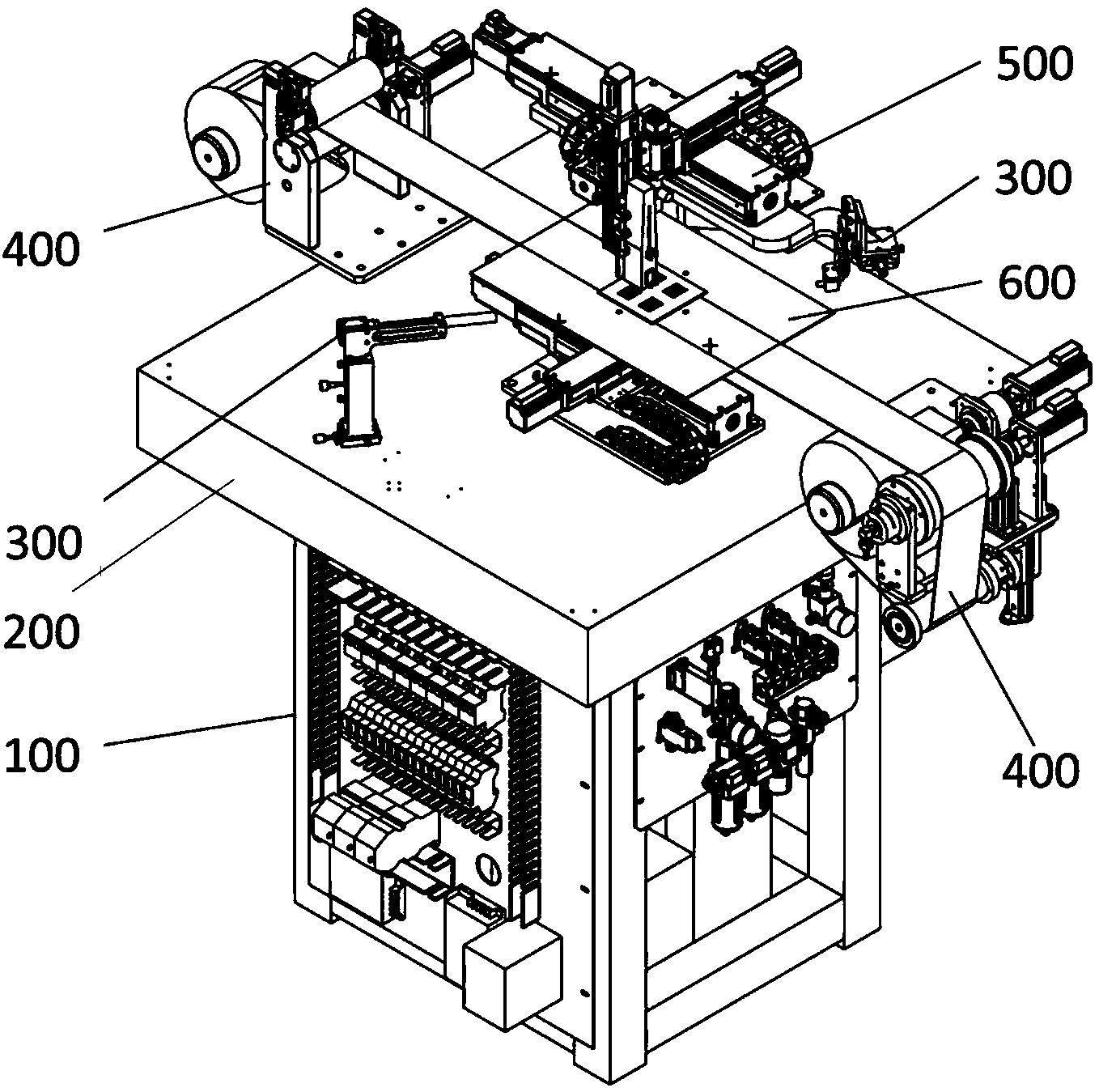
[0091] The printing module 500 and the hard substrate carrying movement module 600 move in cooperation to print patterns on the hard substrate. By adjusting the movement module 600 to initialize it, and the X-axis movement module 602 and the Y-axis movement module 604, the slider moves to the center of its movement stroke. Place hard substrates such as silicon wafers in the center of the adsorption platform, turn on the vacuum pump through the control module, and form negative pressure on the surface of the vacuum platform, the substrate is firmly adsorbed on the adsorption platform, and then adjust the movement of the three movement modules of the printing module 500 , so that the nozzle is facing the edge of the substrate, that is, relative to the zero point of the system. The height of the nozzle from the substrate determines the printing mode, which can be selected according to the needs after being calibrated through experiments. After the specific position is reached, t...

example 2

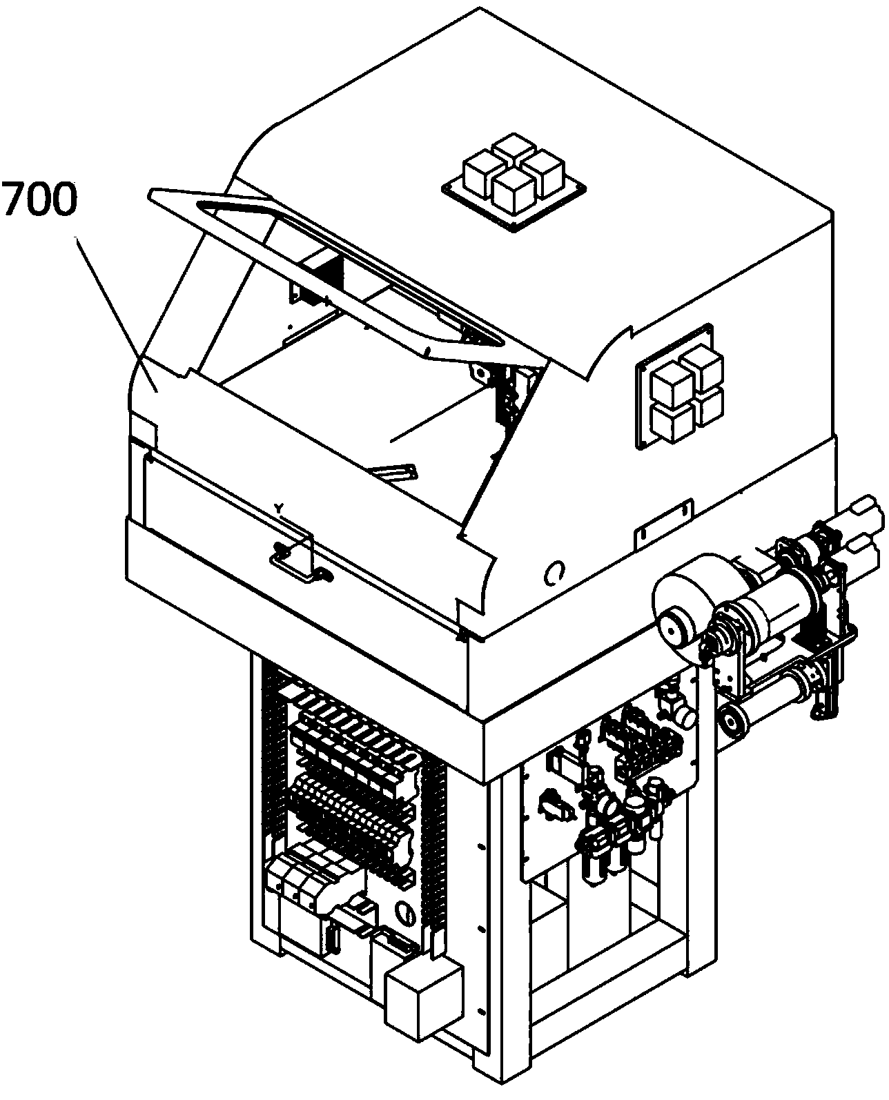
[0093] The roll-to-roll film substrate conveying module 400 cooperates with the jet printing module 500 to print patterns on the flexible substrate. In this working mode, the roll-to-roll film substrate conveying module 400 is responsible for conveying the substrate in a single direction, and the specific printing pattern movement is realized by the jet printing module 500 . Firstly, the material roll is installed on the discharge roller 420 of the front-end discharge part of the roll-to-roll film substrate conveying module 400, passes through the direct gap between the upper and lower rollers of the counter-roller 430, is placed on the adsorption platform, and finally wound on the rear-end receiving part On the rewinding roller, its specific mode and motion state such as Figure 19 shown. Before printing, the hard substrate module returns to the initial position, at this time the thin film substrate is just above the adsorption platform, and then remains in a static state. ...


PUM


Abstract

The invention discloses a system and method for multifunctional high-resolution electric fluid ink-jet printing. The system comprises a control unit, a hard substrate bearing and moving module, a jet printing module, a roll-to-roll thin film substrate conveying module, a jet visual inspection module and a micro-environment control unit defined by a shell box body, wherein the temperature and the humidity of the micro-environment control unit are adjustable. The jet printing module comprises a movement platform controlling a nozzle to move and the nozzle, adjustment and control in three jet printing modes are achieved, and meanwhile a visual system used for observation of patterns on a substrate is arranged. The hard substrate bearing and moving module is used for bearing and fixing a hard printing medium substrate and enabling the substrate to move relative to the nozzle. The roll-to-roll thin film substrate conveying module is used for feeding and adsorbing a flexible substrate and guaranteeing that the surface of the flexible substrate is smooth and the flexible substrate is free of sliding in movement. The jet visual inspection module is used for inspecting a space flight track of a drop. A temperature and humidity control module is used for controlling the temperature and the humidity inside a printing cavity and guaranteeing the printing stability.

Description

technical field [0001] The invention relates to an inkjet printing system, in particular to an inkjet printing device and method driven by electrofluid. Background technique [0002] Inkjet printing equipment has the advantages of friendly manufacturing environment, saving printing materials, and simple operation. In recent years, it has gradually developed from the field of traditional image printing to printing electronics, microfluidics and other fields, such as the use of inkjet printing technology to manufacture flexible electronic transistors and biosensors. , solar cells, microfluidic chips, etc. Traditional inkjet printing technology mainly adopts two modes of continuous printing and on-demand printing, among which on-demand printing includes piezoelectric inkjet and thermal bubble inkjet. The traditional continuous printing method usually uses piezoelectric crystal vibration to generate ink droplets, and then uses the charging electrode to charge the ink, and final...

Claims


Application Information

Patent Timeline
Patent Type & Authority Applications(China)
IPC IPC(8): B41J2/01
CPCB41J3/28B41J3/407B41J25/308H01L31/022425B41J2/072B41J2/145Y02E10/50
Inventor 黄永安尹周平布宁斌陈建魁潘艳桥丁亚江段永青
Owner WUHAN GUOCHUANGKE OPTOELECTRONIC EQUIP CO LTD
Why Eureka
Try Eureka