A plate damping connection structure

A technology of vibration connection and plate parts, which is applied in the field of plate vibration reduction connection structure, can solve the problems of environmental protection performance, noise reduction effect is not significant enough, affect indoor environmental quality, affect ship construction period, etc., achieve obvious vibration reduction effect, improve fire prevention capacity, save the effect of using resistance

Active Publication Date: 2016-03-09
JIANGSU UNIV OF SCI & TECH
View PDF5 Cites 0 Cited by
  • Summary
  • Abstract
  • Description
  • Claims
  • Application Information

AI Technical Summary

Problems solved by technology

Although sound-absorbing materials such as rock wool have a high sound-absorbing coefficient, the existence of tiny particles often affects the quality of the indoor environment. Some sound-absorbing materials have poor performance in terms of anti-corrosion and waterproofing, and are used in ships, automobiles, etc. Indoor use is also restricted
In addition, when the ship's cabin wall structure and floor structure are outfitted inside, it takes a certain amount of construction time, which often affects the ship's construction period.
[0007] Therefore, although the traditional vibration reduction and noise reduction measures adopted on the plate reinforcement structure, such as damping material vibration reduction and sound absorption and noise reduction technologies, although the vibration and noise of ships and automobiles have been reduced to a certain extent, there are still some problems. Due to the use of vibration and noise reduction materials in a large area, it affects the economy, affects the construction period, environmental protection performance, and the noise reduction effect is not significant enough.

Method used


Image

  • A plate damping connection structure
  • A plate damping connection structure

Examples


Embodiment Construction

[0029] The present invention will be described in more detail below in conjunction with accompanying drawing and embodiment, should be understood that embodiment is only for illustrating the present invention and is not intended to limit the scope of the present invention, after having read the document content of the present invention, those skilled in the art will understand the present invention The modifications of various equivalent substitutions all fall within the scope of protection claimed by the present application.

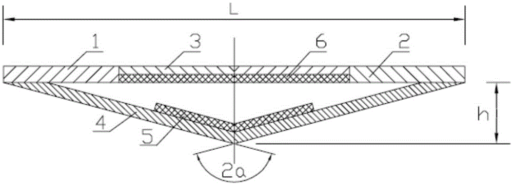
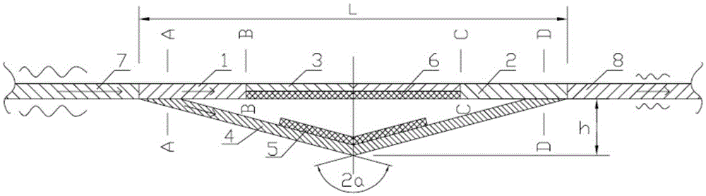
[0030] Such as figure 1 As shown, it is a panel vibration-damping connection structure of the present invention, which is composed of a first connecting plate 1, a second connecting plate 2, an elastic thin plate 3, a V-shaped thin plate 4, a first damping block 5 and a first damping block 6 . Wherein the two ends of the elastic thin plate 3 are butted and fixedly connected with one end of the first connecting plate 1 and the second connecting plate 2 ...


PUM


Abstract

The invention discloses a plate vibration damping connection structure, which is composed of a first connecting plate, a second connecting plate, an elastic thin plate, a V-shaped thin plate, a first damping block and a second damping block, wherein the two ends of the elastic thin plate The first connecting plate and one end of the second connecting plate are butted and fixedly connected to form a flat plate structure, the second damping block is pasted on the bottom plane of the elastic thin plate, and the two ends of the V-shaped thin plate are connected to the two ends of the V-shaped thin plate respectively. The bottom plane of the other end of the first connecting plate and the second connecting plate are fixedly connected to form an overall structure with an isosceles triangle in cross-section, and the first damping block is pasted symmetrically on the inner surface of the V-shaped thin plate. The invention is easy to process and is convenient for modular manufacturing, and can partially replace the stiffeners of the traditional stiffened plate structure, without increasing the weight and thickness and improving the overall bearing capacity of the plate structure, and comprehensively utilizes impedance mismatch vibration resistance, active vibration elimination and The combined design of the damping and vibration reduction principle can significantly improve the vibration reduction effect of the vibration transmission of the plate structure.

Description

technical field [0001] The invention relates to a vibration-damping and noise-reducing structure, in particular to a panel vibration-damping connection structure. Background technique [0002] Vibration and noise are one of the important performance indicators of ships, ships, vehicles and other vehicles. The power machinery in the engine room is the main source of vibration and noise of the ship. When working, the vibration is transmitted to the hull structure of the engine room, and then transmitted to the cabin structure of each layer through the hull structure, generating vibration and noise inside the cabin, which affects the comfort of the crew and other staff, and affects the crew's safety. health, life and work efficiency. In recent years, with the development of the shipping industry, the tonnage, speed and power of the power plant have been continuously increased, making the vibration and noise pollution of the ship cabin increasingly serious, and the vibration an...

Claims


Application Information

Patent Timeline
Patent Type & Authority Patents(China)
IPC IPC(8): B63B3/68
Inventor 温华兵包振明刘林波昝浩
Owner JIANGSU UNIV OF SCI & TECH
Why Eureka
Try Eureka