Glass kiln waste heat recovery system

A waste heat recovery system and glass kiln technology, applied in glass furnace equipment, glass production, glass manufacturing equipment, etc., can solve the problems of underutilized heat, waste, and increased glass production costs, and achieve simple structure and reduced production cost, ease of installation and maintenance

Active Publication Date: 2014-07-02
TIANJIN HUANENG THERMAL EQUIP
View PDF15 Cites 7 Cited by
  • Summary
  • Abstract
  • Description
  • Claims
  • Application Information

AI Technical Summary

Problems solved by technology

[0003] In this case, the exhaust gas of the glass furnace has to be released into the atmosphere through the flue, and the remaining heat is not fully utilized and wasted in vain, which increases the production cost of glass virtually.

Method used


Image

  • Glass kiln waste heat recovery system
  • Glass kiln waste heat recovery system
  • Glass kiln waste heat recovery system

Examples


Embodiment Construction

[0023] The present invention will be further described in detail below in conjunction with the accompanying drawings and through specific embodiments. The following embodiments are only descriptive, not restrictive, and cannot limit the protection scope of the present invention.

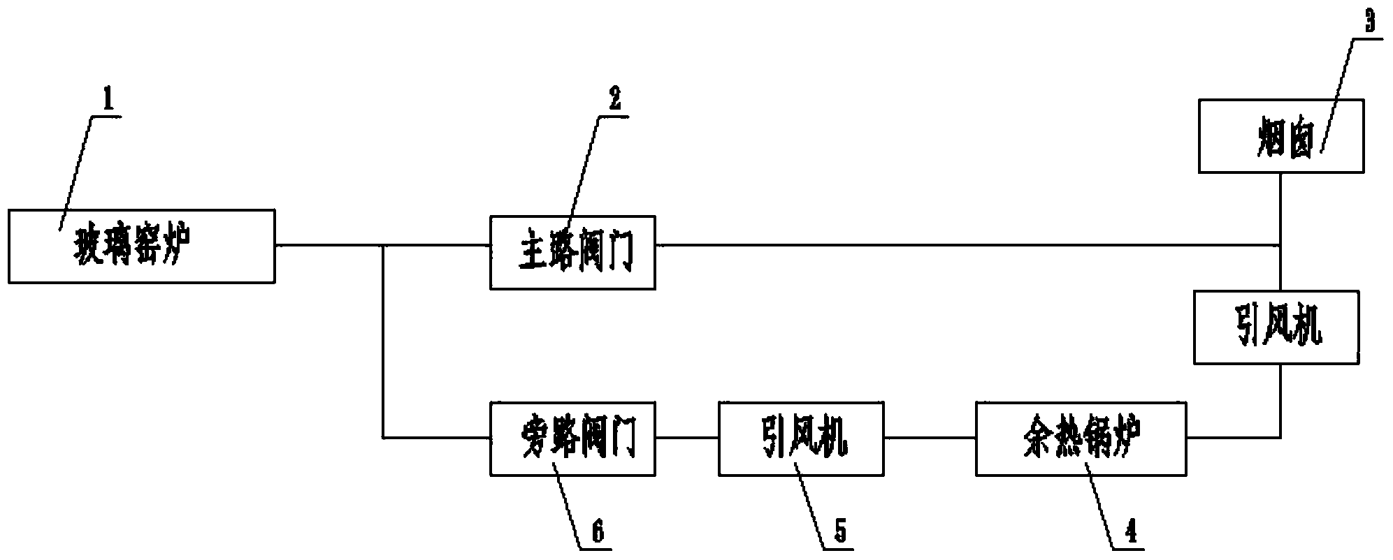
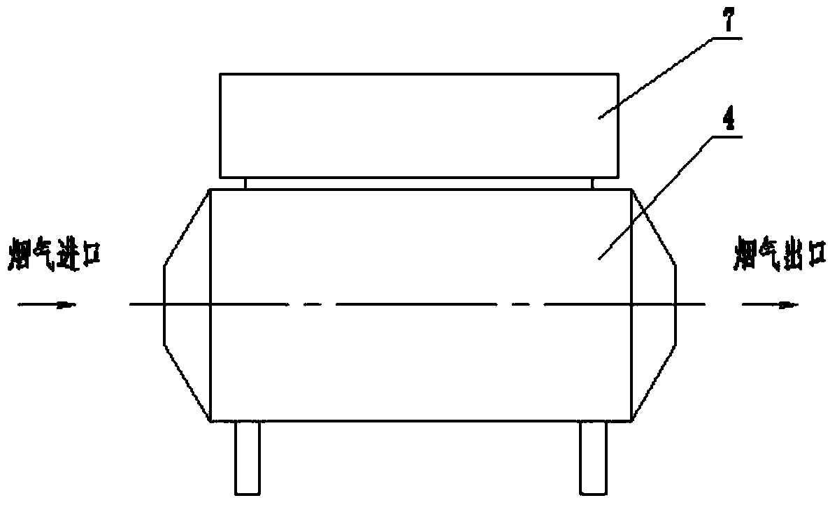
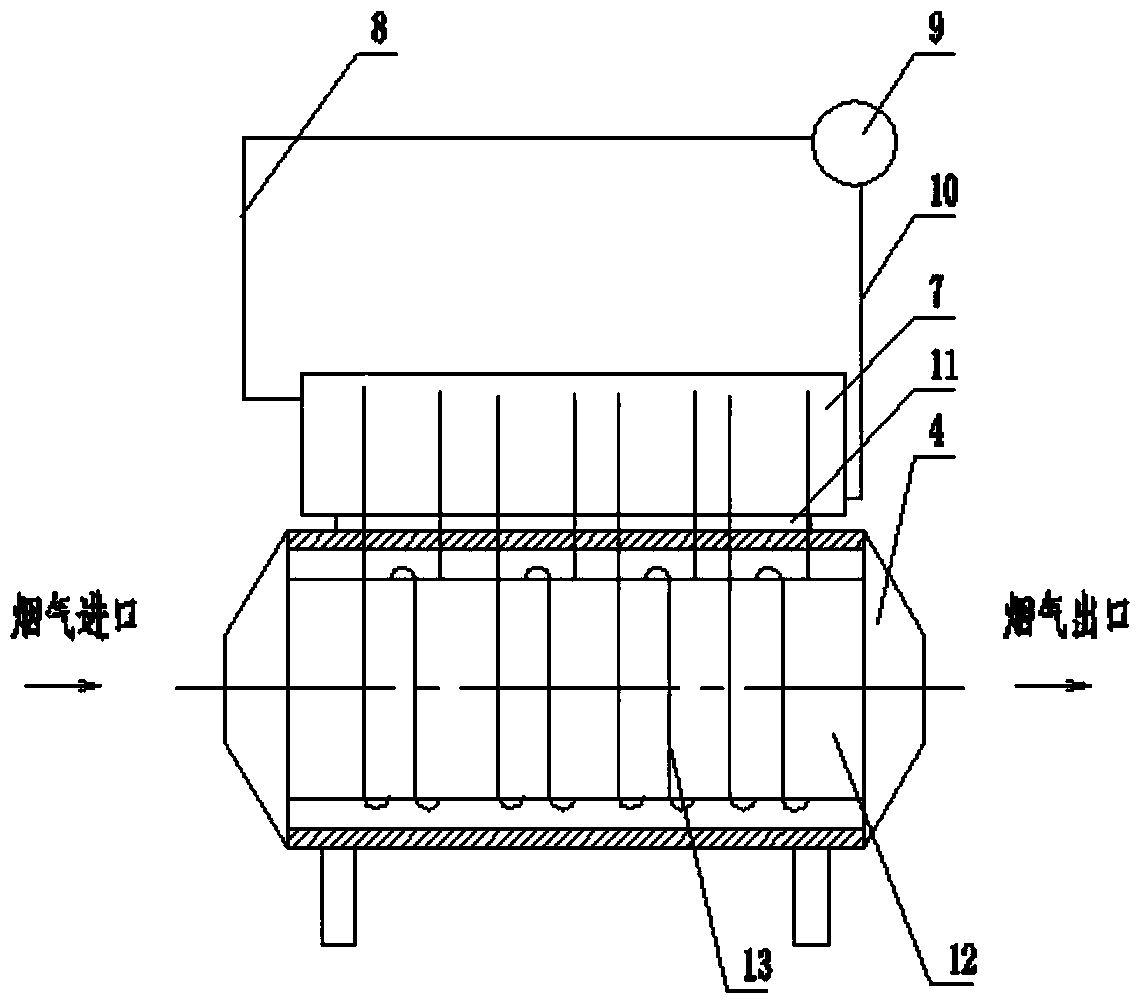
[0024] A waste heat recovery system for a glass kiln, such as figure 1 As shown, it includes a glass furnace 1, an induced draft fan 5 and a waste heat boiler 4. The exhaust port of the glass furnace is connected to a chimney 3 through a main flue, and a main road valve 2 is installed on the main flue. A bypass flue is also connected between the chimneys, and a bypass valve 6, an induced draft fan, a waste heat boiler and an induced draft fan are sequentially installed on the bypass flue. When the waste heat boiler is repaired or breaks down, it will not affect the normal operation of the glass furnace, and induced draft fans are installed at the smoke inlet and smoke outlet of the waste heat furnace...


PUM


Abstract

The invention relates to a glass kiln waste heat recovery system. The glass kiln waste heat recovery system comprises a glass kiln, two induced draft fans and a waste heat boiler, an exhaust port of the glass kiln is connected with a chimney through a main flue, a main path valve is mounted on the main flue, a bypass flue is further arranged between the glass kiln and the chimney, and a bypass valve, one induced draft fan, the waste heat boiler and the other induced draft fan are mounted on the bypass flue sequentially. The waste heat boiler is connected on the bypass flue parallelly, and one valve is mounted on each of the main flue and the bypass flue, so that the glass kiln and the waste heat boiler are enabled not to interfere each other, and normal operation of the system is guaranteed; heat pipes and a boiler chamber of the waste heat boiler in the system are all of a spiral pipe structure, so that heat is increased greatly.

Description

technical field [0001] The invention belongs to the technical field of flue gas waste heat recovery, in particular to a waste heat recovery system of a glass kiln. Background technique [0002] At present, there are more than 200 glass production enterprises in the country, and most of the kilns producing glass use heavy oil, coal and natural gas as the main fuels. Glass furnaces emit a large amount of exhaust gas, high temperature, and high power consumption. The proportion of energy consumption expenditure generally accounts for between 40% and 45% of the total production cost, and more than 30% of the heat energy is discharged in the form of exhaust gas. [0003] In this case, the exhaust gas of the glass furnace has to be released into the atmosphere through the flue, and the remaining heat is not fully utilized and is wasted in vain, which increases the production cost of glass virtually. [0004] After searching, I found a document related to the content of this paten...

Claims


Application Information

Patent Timeline
Patent Type & Authority Applications(China)
IPC IPC(8): F27D17/00F22B1/18C03B5/00
CPCY02P10/25Y02P40/50
Inventor 张宏伟王瑞广王磊钱会敏曹新波李宝江
Owner TIANJIN HUANENG THERMAL EQUIP
Why Eureka
Try Eureka