Permanent magnet speed governor with fixed magnetic gap

A permanent magnet speed governor and fixed magnetic technology, applied in electrical components, electromechanical devices, electromechanical transmission devices, etc., can solve the problems of high power consumption of magnetic circuit regulators, poor torque transmission capacity, waste of rare earth resources, etc., to save Installation space, improved torque transmission capacity, and the effect of saving rare earth materials

Active Publication Date: 2014-07-02
刁俊起
View PDF5 Cites 13 Cited by
  • Summary
  • Abstract
  • Description
  • Claims
  • Application Information

AI Technical Summary

Problems solved by technology

At present, the commonly used permanent magnet governors realize the speed adjustment by adjusting the air gap. The power consumption of the magnetic circuit regula

Method used


Image

  • Permanent magnet speed governor with fixed magnetic gap
  • Permanent magnet speed governor with fixed magnetic gap
  • Permanent magnet speed governor with fixed magnetic gap

Examples


Embodiment 1

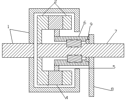
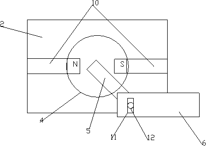
[0027] A permanent magnet governor with a fixed magnetic gap, such as figure 1 , 2 As shown, it includes a cylindrical conductor rotor 1 and a permanent magnet rotor inside. The permanent magnet rotor includes a driven shaft 7 and at least one rotatable permanent magnet 4 arranged circumferentially around the driven shaft 7. The rotatable permanent magnet 4 is cylindrical and has an N pole and an S pole along the diameter direction, and the rotatable permanent magnet 4 is perpendicular to the driven shaft 7 . Both sides of the rotatable permanent magnet 4 are wrapped with a magnetizer 2, and the two magnetizers 2 are separated by a non-magnetizer 10. The rotatable permanent magnet 4 is connected with the driven shaft 7 through the magnetizer 2 on one side, and the rotatable permanent magnet One end of 4 is provided with a magnetic circuit adjuster, and the magnetic circuit adjuster is used to rotate the rotatable permanent magnet 4, adjust its magnetic pole direction and then...

Embodiment 2

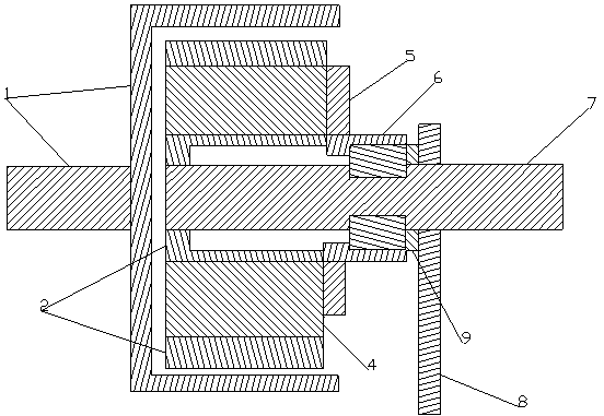
[0029] A permanent magnet governor with a fixed magnetic gap, such as image 3 , 4 As shown, the rotatable permanent magnet 4 is parallel to the driven shaft 7, and other structures are the same as in the first embodiment.

Embodiment 3

[0031] A permanent magnet governor with a fixed magnetic gap, such as Figure 5 , 6As shown, it includes a cylindrical conductor rotor 1 and a permanent magnet rotor inside. The permanent magnet rotor includes a driven shaft 7 and at least one rotatable permanent magnet 4 arranged circumferentially around the driven shaft 7. The rotatable permanent magnet 4 is cylindrical and has an N pole and an S pole along the diameter direction, and the rotatable permanent magnet 4 is perpendicular to the driven shaft 7 . Both sides of the rotatable permanent magnet 7 are wrapped with a magnetizer 2, and the two magnetizers 2 are separated by a non-magnetizer 10. The rotatable permanent magnet 4 is connected with the driven shaft 7 through the magnetizer 2 on one side, and the rotatable permanent magnet One end of 4 is provided with a magnetic circuit adjuster, and the magnetic circuit adjuster is used to rotate the rotatable permanent magnet 4, adjust its magnetic pole direction and then...


PUM


Abstract

The invention relates to a permanent magnet speed governor with a fixed magnetic gap. The permanent magnet speed governor with the fixed magnetic gap comprises a cylindrical conductor rotor and a permanent magnet rotor inside the cylindrical conductor rotor, wherein the permanent magnet rotor comprises a driven shaft and at least one rotary permanent magnet surrounding the circumference of the driven shaft; the rotary permanent magnets are cylindrical and are divided into N poles and S poles in the diameter direction; two magnetizers are wrapped around the two sides of the rotary permanent magnets and are spaced by a non-magnetizer; each rotary permanent magnet is connected with the driven shaft through the magnetizer on the corresponding side; a magnetic circuit regulator is arranged at one end of each rotary permanent magnet. Due to the adoption of the fixed magnetic gap structure, the meshing area of the speed governor is increased greatly, the assembly difficulty is lowered, waste of rear earth materials is reduced, and the torque transmission capacity is improved greatly. In addition, the power consumption of an executing and adjusting mechanism is reduced greatly, the overall size of the speed governor is greatly decreased, material consumption is reduced, installation space is saved, and convenience is brought to on-site installation construction.

Description

technical field [0001] The invention relates to a permanent magnet governor, in particular to a permanent magnet governor with a fixed magnetic gap. Background technique [0002] The permanent magnet speed governor uses the magnetic coupling speed of the permanent magnet to realize the soft (magnetic) connection between the motor and the load, without any harmonic generation affecting the power grid, and has high reliability. , Inflammable and explosive, voltage instability and lightning and other harsh environments, greatly reducing mechanical vibration, widely used in electric power, steel, metallurgy, petrochemical, papermaking, municipal, ships, irrigation and mining industries. At present, the commonly used permanent magnet governors realize the speed adjustment by adjusting the air gap. The magnetic circuit regulator consumes a lot of power, and has disadvantages such as poor torque transmission capability, high assembly difficulty, and waste of a large amount of rare ...

Claims


Application Information

Patent Timeline
IPC IPC(8): H02K51/00
Inventor 刁俊起
Owner 刁俊起
Why Eureka
Try Eureka