Compressor

A technology for compressors and space compression, which is applied in the field of compressors and can solve problems such as refrigerant leakage, increased refrigerant leakage, and unstable performance of the cylinder 43

Active Publication Date: 2014-07-09
LG ELECTRONICS INC
View PDF6 Cites 2 Cited by
  • Summary
  • Abstract
  • Description
  • Claims
  • Application Information

AI Technical Summary

Problems solved by technology

[0021] However, according to the aforementioned prior art 1-cylinder 2-compression chamber compressor, the piston 44 is fixed while the relatively heavy cylinder 43 is rotated, and thus results in higher power loss with respect to the same cooling power and large bearing area, thereby increasing the problem of refrigerant leakage
[0022] Furthermore, according to the 1-cylinder 2-compression chamber compressor in the prior art, a part of the outer peripheral surface of the cylinder 43 is closely attached to the inner peripheral surface of the upper case 41, so the diameter of the upper case 41 should be increased, To change the volume of the cylinder 43 with the rotational movement, and thus the casing 1 itself should be changed in an increasing manner, resulting in the problem that the volume of the compressor is not easy to control
[0023] Furthermore, according to the 1-cylinder 2-compression chamber compressor in the prior art, the first discharge port 41b and the second discharge port 41c may be formed in the same direction, so the refrigerant that is discharged first may cause a so-called pulsation phenomenon, thereby making Increased vibration and noise of the compressor
[0024] In addition, according to the 1-cylinder 2-compression chamber compressor in the prior art, since two compression chambers are formed at the same height, a torque load is unevenly generated as the pressure difference between these two compression chambers changes, whereas Make the performance of the cylinder 43 unstable, causing effects on noise, wear, or refrigerant leakage

Method used


Image

  • Compressor
  • Compressor
  • Compressor

Examples


Embodiment Construction

[0047] Hereinafter, a compressor according to an embodiment of the present invention will be described in detail with reference to the accompanying drawings.

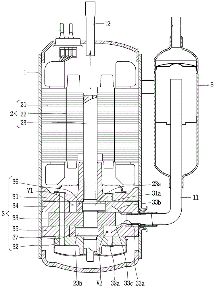
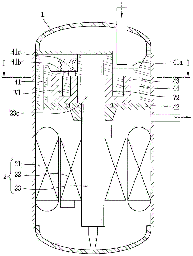
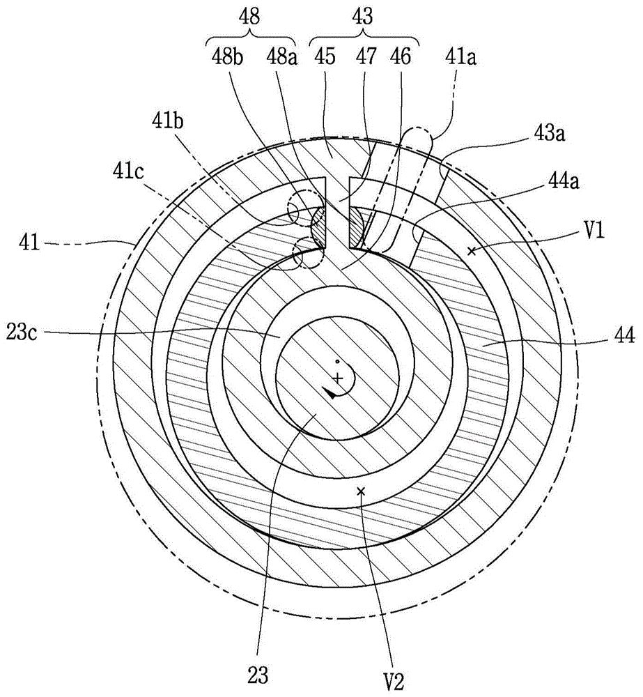
[0048] Figure 4 is a longitudinal sectional view showing a 1-cylinder 2-compression chamber type rotary compressor according to the present application, Figure 5 is shown based on Figure 4 An exploded perspective view of the compression unit in the compressor, Figure 6 is along Figure 4 The sectional view of the line "II-II", Figure 7 is a longitudinal sectional view showing the compression unit in a sectional view along the line "III-III", and Figure 9 is shown according to an embodiment Figure 7 A plan view of a backpressure tank in a compressor in .

[0049] As shown in the drawings, according to the 1-cylinder 2-compression chamber type rotary compressor of the embodiment of the present application, the motor drive device 2 for generating driving force is provided in the inner space of the casing 1, an...


PUM


Abstract

A compressor is provided, and may include a cylinder including an outer cylinder portion and an inner cylinder portion, and a vane portion which is connected between the outer cylinder portion and inner cylinder portion, and is fixed to a casing. A rolling piston may be slidably coupled to the vane portion to form an outer compression space and an inner compression space while making a turning movement between the outer cylinder portion and the inner cylinder portion. Through this, a weight of a rotating body may be reduced to obtain low power loss with respect to a same cooling power and a small bearing area, thereby reducing refrigerant leakage as well as easily changing a capacity of a cylinder in an expanded manner. Moreover, refrigerant may be discharged in opposite directions in each compression space, thereby reducing vibration noise of the compressor. In addition, a back pressure groove may be formed on an upper surface of a drive transmission portion of the rolling piston, thereby reducing a friction area between the rolling piston and the upper bearing, as well as reducing a friction loss between the rolling piston and the upper bearing due to oil filled into the back pressure groove.

Description

technical field [0001] The present invention relates to a compressor, and more particularly, to a 1-cylinder 2-compression chamber compressor in which two compression spaces are formed in one cylinder. Background technique [0002] In general, a compressor can be applied to a vapor compression refrigeration cycle (hereinafter, abbreviated as "refrigeration cycle") such as a refrigerator, an air conditioner, or the like. For the refrigerant compressor, a constant speed compressor driven at a predetermined speed or an inverter type compressor in which a rotational speed is controlled has been used. [0003] Compressors can be classified into: hermetic compressors, in which a motor drive, which is typically an electric motor, and a compression unit operated by the motor drive are disposed together in the inner space of a sealed casing; and open compressors , wherein the motor is separately provided outside the casing. Hermetic compressors are mainly used in domestic or commer...

Claims


Application Information

Patent Timeline
Patent Type & Authority Applications(China)
IPC IPC(8): F04C29/00
CPCF01C21/08F04C18/045F04C23/008F04C2/356F04C18/00F04C18/356F04C2/34F04C15/0065
Inventor 文石焕史范东李丙哲
Owner LG ELECTRONICS INC
Why Eureka
Try Eureka