Infrared imaging detecting system through optical fiber coupling between QWIP-LED and EMCCD

A QWIP-LED, infrared imaging technology, applied in the coupling of optical waveguides, optical radiation measurement, measuring devices, etc., can solve the problems of low light emission rate, low optical efficiency of near-infrared systems, etc., and achieve high optical coupling efficiency and infrared detection. The effect of increasing the rate and reducing the size

Inactive Publication Date: 2014-07-09
SHANGHAI INST OF TECHNICAL PHYSICS - CHINESE ACAD OF SCI
View PDF5 Cites 4 Cited by
  • Summary
  • Abstract
  • Description
  • Claims
  • Application Information

AI Technical Summary

Problems solved by technology

[0004] Near-infrared optical systems are generally implemented using traditional optical solutions. The disadvantage is that the optical efficiency of near-infrared systems is low, which is manifested in two aspects: First, because QWIP-LED has a high material refractive index (QWIP-LED is about 3.5) , most of the emitted near-infrared light is fully emitted at the interface between the LED and the air, making the light emission rate extremely low, which is lower than 2% (1 / n2) for QWIP-LED devices; secondly, for QWIP-LED devices For the near-infrared light successfully emitted by the LED, the collection capacity of the traditional optical system is only 10% at most, so that the near-infrared light that finally reaches the EMCCD is less than 0.2%
Low optical efficiency is the main factor restricting the wide engineering application of QWIP-LED. How to improve the optical efficiency of infrared imaging detection system based on QWIP-LED is an important research topic for researchers.

Method used


Image

  • Infrared imaging detecting system through optical fiber coupling between QWIP-LED and EMCCD
  • Infrared imaging detecting system through optical fiber coupling between QWIP-LED and EMCCD
  • Infrared imaging detecting system through optical fiber coupling between QWIP-LED and EMCCD

Examples


Embodiment Construction

[0025] Design and build the system according to the system structure described in the manual.

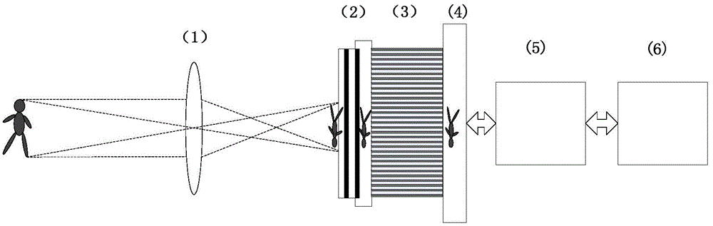
[0026] The design of the long-wave infrared optical system 1 is carried out according to the design method of the traditional optical system, and the corresponding optical parameters such as field of view, F number and focal length are designed according to different application scenarios. The imaging focal plane is the plane where the QWIP-LED is located.

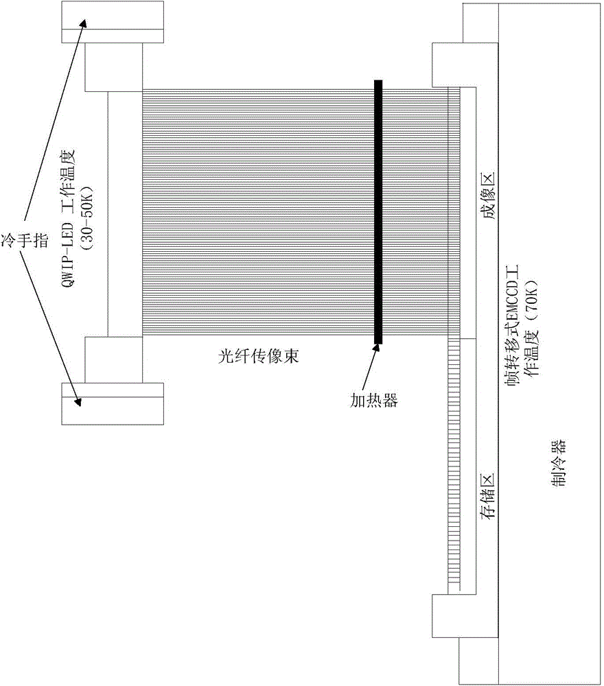
[0027] QWIP-LED2 selection. Select the transmissive QWIP-LED type with higher infrared absorption efficiency and internal quantum efficiency. In the process of device customization, its effective area only needs to be equivalent to the area of ​​the photosensitive surface of EMCCD. Provides the DC bias voltage required for normal operation of the QWIP-LED.

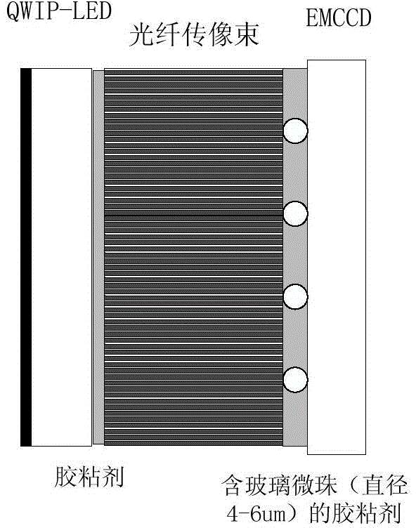
[0028] Fiber optic image bundle 3 options. The length is not strictly limited, and can be adjusted according to factors such as cooling difficulty; the diameter of a sing...


PUM


Abstract

The invention discloses an infrared imaging detecting system through optical fiber coupling between a QWIP-LED and an EMCCD. According to the system, an optical fiber image transmission bundle is used for coupling near-infrared images obtained by QWIP-LED infrared up converting to the EMCCD for imaging, and EMCCD detecting of a long-wave infrared target is achieved. The system has the advantages that the transmission efficiency of infrared images from the QWIP-LED to the EMCCD can be effectively improved through the optical fiber image transmission bundle, accordingly the detecting efficiency of the system is high, and in addition, the space size of the detecting system can be obviously reduced.

Description

Technical field: [0001] This patent relates to an infrared imaging detection system. Specifically, it refers to an infrared imaging detection system using optical fiber coupling between QWIP-LED and EMCCD. This technology can be used in the field of long-wave infrared imaging detection. Background technique: [0002] Infrared up-conversion technology has always been a research hotspot for researchers from various countries. Its purpose is to convert the target's medium and long-wave infrared radiation into near-infrared or visible light image information, and then use commercial CCD or CMOS for imaging, replacing expensive Traditional infrared area array detector. Existing infrared up-conversion technologies include thermally stimulated infrared up-conversion, parametric infrared up-conversion, rare earth material infrared up-conversion, and PD-LED infrared up-conversion technology. PD-LED has significant advantages in terms of process cost, quantum efficiency, response ba...

Claims


Application Information

Patent Timeline
Patent Type & Authority Applications(China)
IPC IPC(8): G02B6/43G01J5/08
Inventor 侯义合张冬冬丁雷刘加庆谭婵朱学谦周巨广
Owner SHANGHAI INST OF TECHNICAL PHYSICS - CHINESE ACAD OF SCI
Why Eureka
Try Eureka