Rapid molten iron conveying method and device combination between interfaces of molten iron and molten steel

A molten iron and interface technology, applied in industrial buildings and other fields, can solve problems such as long operation time, increased investment, and long railway lines

Active Publication Date: 2014-07-16
SHANDONG PROVINCE METALLURGICAL ENG CO LTD
View PDF6 Cites 10 Cited by
  • Summary
  • Abstract
  • Description
  • Claims
  • Application Information

AI Technical Summary

Problems solved by technology

[0002] At present, the interface between the blast furnace and the converter in the metallurgical industry is far away. When the molten iron from the blast furnace is transported to the converter, the torpedo tanker or molten iron tanker filled with molten iron is usually transported to the converter workshop by train. The line is long and occupies a large area; there are many locomotives and tank cars, and the investment in equipment is large; under the blast furnace casting yard, it is necessary to wait for multiple tank cars to be filled with molten iron before transporting to the converter. When arriving at the converter workshop, the molten iron in each tank needs to be mixed into The converter can only be returned to the casting yard after all the tanks are emptied. The tanks wait for a long time in the blast furnace and converter, and the molten iron cools down greatly, which is not conducive to energy saving; the transportation link consumes a lot of power
CN102004815A discloses a method for optimizing the interface mode of "one tank to the bottom" in the blast furnace-converter section of an iron and steel enterprise, and carries out real-time tracking and online monitoring and diagnosis of the production process of the "one tank to the bottom" interface mode in the blast furnace-converter section to reduce The waiting time before entering the converter, but only optimized on the basis of the existing railway train transportation, the waiting

Method used


Image

  • Rapid molten iron conveying method and device combination between interfaces of molten iron and molten steel
  • Rapid molten iron conveying method and device combination between interfaces of molten iron and molten steel
  • Rapid molten iron conveying method and device combination between interfaces of molten iron and molten steel

Examples


Embodiment 1

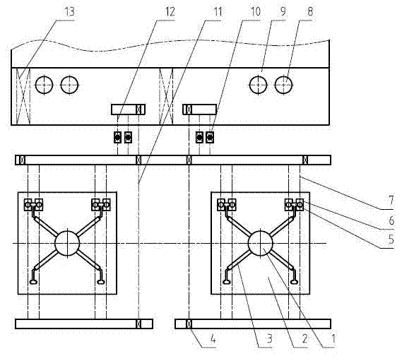
[0058] The combination of equipment between molten iron and molten steel interface, such as figure 1 As shown, it includes blast furnace 1, blast furnace casthouse 2, molten iron transportation unit 6, molten iron transportation line (7, 11, 12), converter 8,

[0059] The molten iron transportation line is arranged between the center line of blast furnace 1 and the center line of converter 8; blast furnace casting house 2 is located at the lower part of blast furnace 1, and molten iron transportation line 7 is arranged on the side of blast furnace casting house 2;

[0060] From the blast furnace casting yard 2 to the converter charging span 9, there is at least one discontinuity in the molten iron transportation line (7, 11, 12), and the molten iron transportation line is divided into the molten iron transportation line 7 on the blast furnace side and the molten iron transportation line on the converter side 12. The molten iron transportation line 7 on the blast furnace side i...

Embodiment 2

[0069] Others are as embodiment 1, the difference is that,

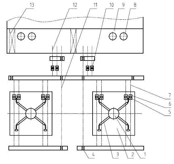
[0070] Such as figure 2 As shown, the molten iron desulfurization station 10 is arranged outside the charging bay of the converter workshop, a transition device 4 is provided between the charging bay of the converter workshop and the molten iron desulfurization station 10, and a transition device 4 is provided at the end of the molten iron transportation line on the side of the blast furnace away from the converter, A separate molten iron return travel line 11 is set outside the molten iron transport line.

[0071] The molten iron transportation unit 6 travels to the molten iron desulfurization station 10 for desulfurization operation of the molten iron. After desulfurization, the molten iron transportation unit 6 travels to the charging bay of the converter workshop, and waits for the molten iron in the molten iron tank to be loaded into the converter 8 by the converter charging span crane 13 .

[0072] The molten...

Embodiment 3

[0074] Others are the same as embodiment 1, the difference is that

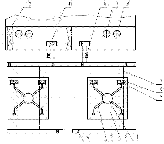
[0075] Such as image 3 As shown, a transition device 4 is provided in the charging span 9 of the converter workshop, and no separate molten iron return travel line 11 is provided. The transport unit 6 filled with molten iron in the charging span 9 moves to another molten iron transport line 12 near the converter without a desulfurization station through the transition device 4 in the span, and waits for the last molten iron transport unit 6 filled with molten iron After moving to the desulfurization station 10 through the transition device 4, the waiting molten iron transport units 6 return to the casthouse 2 respectively through the transition device 4, and are positioned to wait for receiving molten iron.


PUM


Abstract

The invention relates to a rapid molten iron conveying method and a device combination between interfaces of molten iron and molten steel and belongs to the technical field of metallurgical industry. A molten iron conveying line is configured between a blast furnace or a blast furnace group center line and a converter or a converter group center line, and the molten iron conveying line is configured on one side of a blast furnace casting house; from the blast furnace casting house down into a converter charging aisle, the molten iron conveying line is provided with at least one interruption to divide the molten iron conveying line into a blast furnace side molten iron conveying line and a converter side molten iron conveying line which are connected with each other through a transition device, a molten iron conveying unit consists of a molten iron conveying carrier vehicle and a molten iron jar located on the molten iron conveying carrier vehicle, and the molten iron conveying unit is operated on the molten iron conveying line from the blast furnace casting house down into a converter workshop. According to the rapid molten iron conveying method and the device combination between the interfaces of molten iron and molten steel, a molten iron conveying mode from the blast furnace to a converter is changed, layout of conveying lines is changed, and purposes of saving investment and reducing energy consumption are achieved.

Description

technical field [0001] The invention relates to a method for rapidly transporting molten iron between molten iron and molten steel interfaces, and belongs to the technical field of metallurgical industry. Background technique [0002] At present, the interface between the blast furnace and the converter in the metallurgical industry is far away. When the molten iron from the blast furnace is transported to the converter, the torpedo tanker or molten iron tanker filled with molten iron is usually transported to the converter workshop by train. The line is long and occupies a large area; there are many locomotives and tank cars, and the investment in equipment is large; under the blast furnace casting yard, it is necessary to wait for multiple tank cars to be filled with molten iron before transporting to the converter. When arriving at the converter workshop, the molten iron in each tank needs to be mixed into The converter can only be returned to the casting yard after all t...

Claims


Application Information

Patent Timeline
IPC IPC(8): E04H5/02
Inventor 姚朝胜陈诚焉永刚于国华王洪军李奇武魏新民
Owner SHANDONG PROVINCE METALLURGICAL ENG CO LTD
Why Eureka
Try Eureka