Backlight module and liquid crystal display device

A technology for liquid crystal display devices and liquid crystal panels, which is applied to lighting devices, fixed lighting devices, cooling/heating devices for lighting devices, etc., can solve problems such as poor heat dissipation performance, easy burns to users due to the temperature of the front case, and impact on heat dissipation effects.

Active Publication Date: 2014-07-16
HISENSE VISUAL TECH CO LTD
View PDF7 Cites 21 Cited by
  • Summary
  • Abstract
  • Description
  • Claims
  • Application Information

AI Technical Summary

Problems solved by technology

[0005] In the process of implementing this solution, the inventors found that since the COF heat sink 8 is attached to the inner wall of the plastic front shell side wall 101, the size of the front shell side wall 101 limits the size of the COF heat sink 8 and affects the heat dissipation area, and the front shell is The heat dissipation performance of plastic materials is poor, which affects the heat dissipation effect, and because it is directly attached to the side wall of the shell cover, most of the heat is dissipated outward through the part of the front shell, so that the temperature of the front shell is high and it is easy to burn the user

Method used


Image

  • Backlight module and liquid crystal display device
  • Backlight module and liquid crystal display device
  • Backlight module and liquid crystal display device

Examples


Embodiment 1

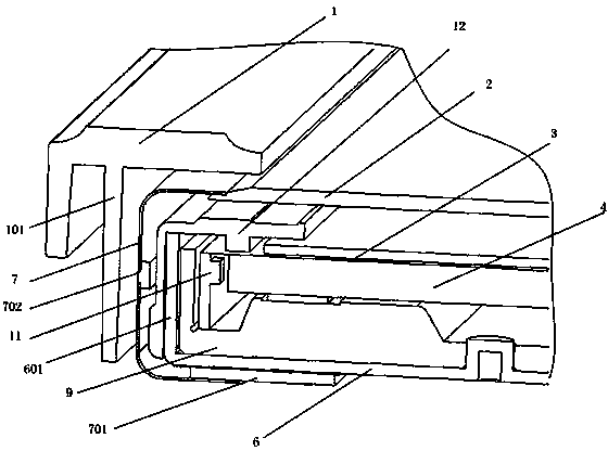
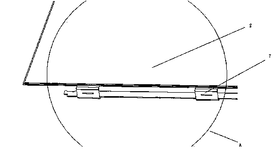
[0034] This embodiment provides a liquid crystal display device, such as Figure 7 As shown, it includes: the back plate 6 including the back plate flange 601 around and the inner cavity surrounded by the bottom plate, the plastic frame 12, the diaphragm assembly 3, the light guide plate 4, the liquid crystal panel 2, and the light source assembly 11 with LED lights set on the PCB board The light source assembly 11 is arranged on the inner wall of the back panel flange 601 of the back panel 6 through the LED lamp cooling fin 9, wherein the LED lamp cooling fin 9 made of L-shaped aluminum material is accommodated in the inner cavity of the back panel 6, One folded side of the L-shaped LED lamp heat sink 9 is connected to the PCB board of the light source 11, and the other side is connected to the back plate folded edge 601 of the back plate 6, and the bottom surface of the other folded edge of the L-shaped LED lamp heat sink 9 is fixed. On the bottom surface of the inner cavity...

Embodiment 2

[0045] In this embodiment, a side-type backlight module is provided, such as Figure 7 As shown, it includes: the backboard 6 surrounded by the backboard flange 601 and the inner cavity surrounded by the bottom board, the plastic frame 12, the diaphragm assembly 3, the light guide plate 4, the liquid crystal panel 2, and the light source assembly 11 with the LED lamp set on the PCB board, The light source assembly 11 is arranged on the inner wall of the back panel flange 601 of the back panel 6 through the LED lamp cooling fin 9, wherein the LED lamp cooling fin 9 made of L-shaped aluminum material is accommodated in the inner cavity of the back panel 6, L One side of one folded edge of the L-shaped LED lamp heat sink 9 is connected to the PCB board of the light source 11, and the other side is connected to the back plate folded edge 601 of the back plate 6, and the bottom surface of the other folded edge of the L-shaped LED lamp heat sink 9 is fixed on On the bottom surface o...

Embodiment 3

[0051] In this embodiment, a direct-type backlight module (not shown) is provided. Those skilled in the art know that the direct-type backlight module is different from the side-type backlight module. The only difference from the embodiment is that the light guide plate Replace it with a diffuser plate, and set the light source assembly 11 in the inner cavity of the back plate 6, set the diffuser plate in the inner cavity, and set a support frame for supporting the diffuser plate on the bottom plate of the back plate 6, and the other parts are the same as the implementation Example 2 is the same and will not be repeated here.

[0052] It should be noted that the above-mentioned liquid crystal display device may specifically be any product or component with a display function such as a liquid crystal television, a liquid crystal display, a digital photo frame, a mobile phone, and a tablet computer.

[0053] In the description of the various embodiments above, specific features,...


PUM


Abstract

The invention discloses a backlight module and a liquid crystal display device, and relates to the technical field of liquid crystal display. The backlight module and the liquid crystal display device solve the problem of how to achieve a better radiating effect and lower the local temperature of a cover of a shell on the situation that resolution and refreshing frequency of a liquid crystal module are improved and the IC temperature of a COF chip is increased. The liquid crystal display device comprises a Source drive circuit board used for being connected with a liquid crystal panel and arranged on the outer wall of a bottom plate of a back plate, and a COF wound around the outside of a glue frame, wherein the COF is provided with a chip IC. An S plate shielding cover comprises a first folding edge connected with the out wall of the bottom plate of the back plate, and a second folding edge arranged on the periphery of the COF, wherein the first folding edge covers the Source drive circuit board, the second folding edge covers the portion, with the chip IC, of the COF, and a gap exists between the first folding edge and the Source drive circuit board.

Description

technical field [0001] The invention relates to the technical field of liquid crystal display, in particular to a backlight module and a liquid crystal display device. Background technique [0002] The backlight module is divided into side-type backlight module and direct-type backlight module according to the position of the light source. Among them, the side-type backlight module installs the light source on the sides, and the light diffuses through the light guide plate to emit light evenly. The advantage is that the overall thickness is relatively thin, and the light source of the direct-type backlight module is installed in the inner cavity at the bottom of the backplane. [0003] see figure 1 , the side-entry backlight module in the prior art includes: a backplane 6, a plastic frame 12, a diaphragm group 3, a light guide plate 4, and a light source 11 for an LED lamp arranged on a PCB, and the light source assembly 11 passes through the LED lamp heat sink 9 It is arr...

Claims


Application Information

Patent Timeline
Patent Type & Authority Applications(China)
IPC IPC(8): F21S8/00F21V29/00G02F1/13357F21V29/74
Inventor 陆宾林唐志强马骥
Owner HISENSE VISUAL TECH CO LTD
Why Eureka
Try Eureka