Silicon wafer aligning method

A silicon wafer alignment and silicon wafer technology, applied in the direction of optics, instruments, photoplate making process of pattern surface, etc., to achieve the effect of improving the efficiency of fine alignment, reducing the loss of the workpiece table, and improving the efficiency of the whole machine

Active Publication Date: 2014-07-16
SHANGHAI MICRO ELECTRONICS EQUIP (GRP) CO LTD
View PDF7 Cites 2 Cited by
  • Summary
  • Abstract
  • Description
  • Claims
  • Application Information

AI Technical Summary

Problems solved by technology

[0021] For specific problems, using the simple bending algorithm of the existing technical solution, the total distance exceeds 1500 mm

Method used

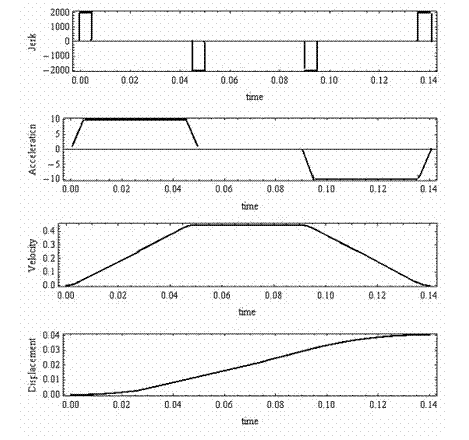
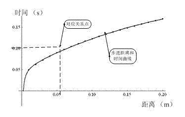
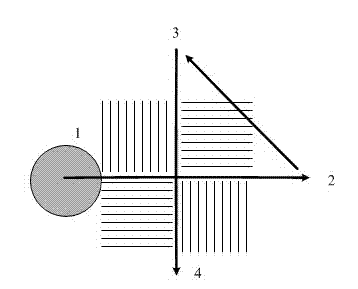

Image

  • Silicon wafer aligning method
  • Silicon wafer aligning method
  • Silicon wafer aligning method

Examples


Embodiment Construction

[0048] Specific embodiments of the present invention will be described in detail below in conjunction with the accompanying drawings.

[0049] In order to better illustrate the technical solution, the following definitions will be made below to help understand the technical solution.

[0050] Wafer Alignment (WA): The function of the wafer alignment device is to complete the horizontal alignment of the silicon wafer and the mask. The radiation beam B is incident on the patterning device (eg mask) MA held on a support structure (eg mask table) MT and is patterned by the patterning device. After having passed through the patterning device (eg mask) MA, the radiation beam B passes through a projection system PS which focuses the radiation beam onto a target portion C of the substrate w. With the help of a second positioner PW and a position sensor IF (e.g. an interferometric device, a linear encoder or a capacitive sensor), the substrate table WT can be moved precisely, e.g. in ...


PUM


Abstract

The present invention discloses a silicon wafer aligning method, which comprises: 1, inputting the position of a precise aligning coordinate point on a silicon wafer, and an upper coordinate and a lower coordinate of movement of a precise aligning process work-piece table; 2, adopting the distances between the previous working positions and the next working positions of the precise aligning process as a constraint function of the zero distance, or finding the nearest neighbor points between the previous working positions and the next working positions of the precise aligning process and connecting the nearest neighbor points so as to be adopted as the constraint function, adopting a traveling salesman algorithm to optimize, and increasing a penalty function as a weight when meeting the constraint condition; 3, adopting a search algorithm to carry out problem calculation; and 4, outputting the calculation result.

Description

technical field [0001] The invention relates to the field of integrated circuit equipment manufacturing, in particular to a method for aligning silicon wafers used in photolithography equipment. Background technique [0002] In the field of lithography machines, the production rate of the whole machine is one of the three core indicators of lithography machines. In order to improve the production rate, various lithography machine manufacturers continue to work hard to tap the potential. In the prior art, a double workpiece table system was invented. Among them, the 16 alignment marks on the silicon wafer are finely aligned at the measurement position of the whole machine to improve the alignment accuracy. [0003] In the field of ultra-large integrated circuit manufacturing, in order to solve the path optimization problem of complex multi-point punching, for example, US Patent No. 7,054,798 proposes an approximate calculation of a single punching path in a plane combined wit...

Claims


Application Information

Patent Timeline
Patent Type & Authority Applications(China)
IPC IPC(8): G03F9/00G03F7/20
Inventor 吴飞李术新李运锋束奇伟
Owner SHANGHAI MICRO ELECTRONICS EQUIP (GRP) CO LTD
Why Eureka
Try Eureka