Supercharge Your Innovation With Domain-Expert AI Agents!

Equipment for handling airflow

A kind of equipment, technology of exhaust gas flow, applied in the direction of gas treatment, electrical components, chemical/physical process, etc., can solve the problem of expensive, non-working plasma burner, etc.

Active Publication Date: 2016-08-24
EDWARDS LTD
View PDF5 Cites 0 Cited by
  • Summary
  • Abstract
  • Description
  • Claims
  • Application Information

AI Technical Summary

Problems solved by technology

However, this is an expensive solution for this kind of problem, since the expensive plasma burner remains off most of the time

Method used


Image

  • Equipment for handling airflow
  • Equipment for handling airflow
  • Equipment for handling airflow

Examples


Embodiment Construction

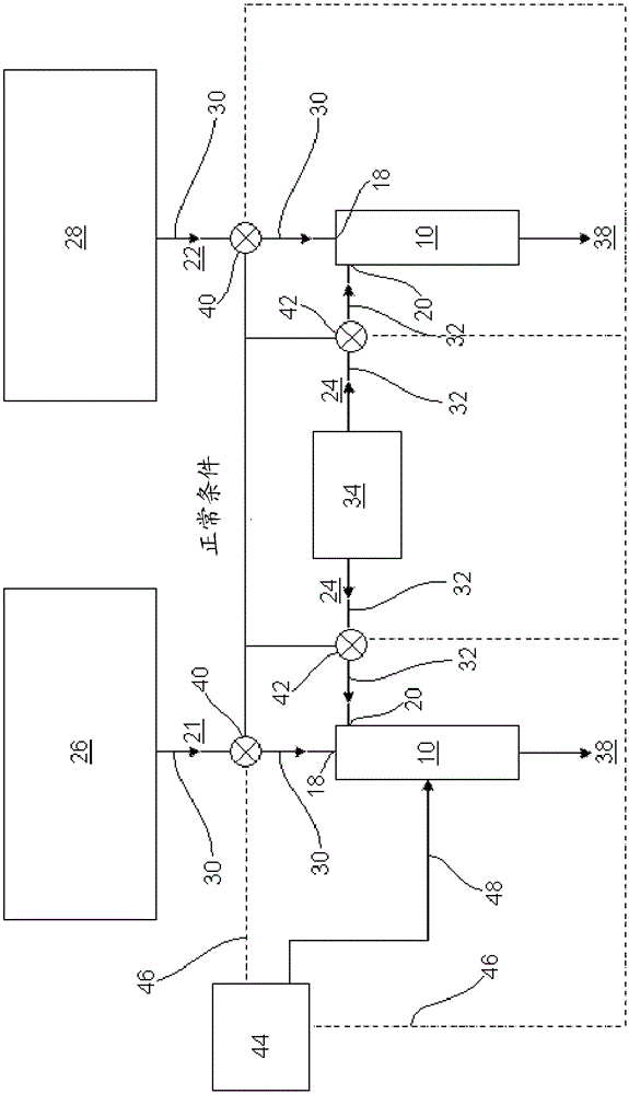
[0021] figure 1 with figure 2 Is a schematic illustration of a plasma abatement apparatus 10 forming part of an apparatus for treating gas streams. Apparatus 10 includes a plasma generator or torch 12 or a reaction chamber 14 . The torch provides a plasma flame 16 for processing slave process chambers (see image 3 , Figure 4 , Figure 7 with Figure 8 ) airflow delivered to the device. The plasma device is preferably a DC plasma device comprising a DC plasma torch such as that described in EP1715937. The chamber 14 has a first inlet 18 and a second inlet 20 . exist figure 1 Under normal conditions of the apparatus shown, the first inlet 18 is in fluid communication with the process chamber. A process gas stream 22 exhausted from the process chamber is flowed into the reaction chamber 14 and plasma flame 16 via the inlet 18 . A second inlet 20 is connected to a reagent source 24, usually oxygen (see image 3 , Figure 4 , Figure 7 with Figure 8 ) into fluid c...


PUM


Abstract

The invention provides an apparatus for treating a gas stream (22). The plasma elimination device (10) has a reaction chamber (14) and a plasma torch (12), the plasma torch (12) is used to generate a plasma flow to be injected into the chamber for processing the gas flow. The first inlet (18) delivers gas flow into the plasma abatement means for processing; and the second inlet (20) is in flow communication with a reagent source under normal conditions of the apparatus for delivering reagent (24) into the plasma means for Improve processing efficiency. In the backup condition of the apparatus, the second inlet is in flow communication with the gas flow source to deliver the gas flow into the device for processing.

Description

technical field [0001] The invention relates to devices for treating air streams. The invention is particularly applicable to the treatment of gas streams exiting process chambers, such as are used in the semiconductor, solar or flat panel display industries. Background technique [0002] One step in the manufacture of semiconductor devices is the formation of thin films on semiconductor substrates by chemical reactions of vapor precursors. One known technique for depositing thin films on substrates is chemical vapor deposition (CVD), which is usually plasma enhanced. In this technique, a process gas is supplied to a process chamber, which houses the substrate, where the process gas reacts to form a thin film on the surface of the substrate. Examples of gases supplied to the process chamber to form thin films include (but are not limited to): silane and ammonia to form silicon nitride films; silane, ammonia, and nitrous oxide to form SiON films; One of oxygen and ozone an...

Claims


Application Information

Patent Timeline
Patent Type & Authority Patents(China)
IPC IPC(8): B01D53/32
CPCB01D53/32B01D2258/0216B01D2259/818H01J37/32009H05H1/24B01D53/005B01J19/088B01J2219/0894
Inventor S.A.沃罗宁J.L.伯德A.A.钱伯斯
Owner EDWARDS LTD
Features
  • R&D
  • Intellectual Property
  • Life Sciences
  • Materials
  • Tech Scout
  • Unparalleled Data Quality
  • Higher Quality Content
  • 60% Fewer Hallucinations
Learn More