Machining method for epicycloid gear

A technology of cycloid bevel gear and processing method, which is applied to gear tooth manufacturing tools, components with teeth, metal processing equipment, etc. The effect of simplifying the structure, simplifying the structure of the machine tool, and improving the accuracy

Active Publication Date: 2014-07-23
TIANJIN TEEK TRANSMISSION
View PDF4 Cites 13 Cited by
  • Summary
  • Abstract
  • Description
  • Claims
  • Application Information

AI Technical Summary

Problems solved by technology

[0007] 1) Klingelnberg adopts a split cutter head. The inner and outer cutter teeth are respectively installed on two independent cutter bodies, which are embedded and stacked together. The eccentricity of the inner and outer cutter bodies is realized through the cross slider mechanism. The structure is extremely complicated and the design and processing are difficult.
The structure of the split cutter head and the cross slider leads to poor rigidity of the machine tool. At the same time, the split cutter head cannot perform high-speed dry cutting;
[0008] 2) Oerlikon adopts the tool tilting method to overcome the defect of "restraint", but the machine tool is equipped with a tool tilting tool rotation mechanism, the machine tool structure is complicated and the calculation and adjustment are complicated;
[0009] 3) The traditional Klingelnberg and Oerlikon methods cannot directly specify the position of the contact area, and repeated trial cutting is required, and it is difficult to control the contact spots and motion curves of the gear pair

Method used


Image

  • Machining method for epicycloid gear
  • Machining method for epicycloid gear
  • Machining method for epicycloid gear

Examples


Embodiment 1

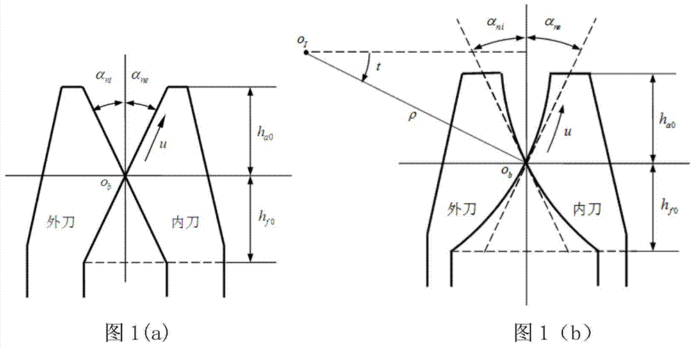
[0043] refer to Figure 4 ,in, Figure 4 (a) is a schematic diagram of the inner edge of a right-handed cutterhead, Figure 4 (b) is a schematic diagram of the outer edge of a right-handed cutterhead, assuming that the gear secondary shaft intersection angle Σ=90°, and the offset distance a v =25mm, number of gear teeth z 2 =39, the number of teeth of the small wheel z 1 =8, outer pitch circle diameter of big wheel d 02 =265mm, midpoint helix angle β m =34.63°, average pressure angle α n =21.5°, tooth width b 2 =40mm, cutterhead radius r c =106.5mm, number of cutter head z 0 =5, small wheel inner knife α ni =22°, small wheel outer knife α ne =20.5°, the big wheel cutter adopts a straight blade, and the pressure angle is opposite to that of the small wheel.

[0044] The specific implementation is as follows:

[0045] (1) Determine the basic parameters of the shape wheel

[0046]

[0047] The midpoint radius Rm is equal to the midpoint taper distance of the gear ...


PUM


Abstract

The invention discloses a machining method for an epicycloid gear. The machining method comprises the steps that (1) basic parameters of a generating gear are determined; (2) the motion mode forming the tooth surface of the generating gear is determined; (3) generating gear tooth surface shape correction is determined; (4) a tool path for forming the tooth surface of the generating gear is planned; (5) the motion through which the generating gear generates the gear is determined; (6) generation of the machined gear is completed. The machining method for the epicycloid gear has the advantages that compared with the Klingelnberg method, the structure of a cutterhead is greatly simplified, no crosshead shoe mechanisms are needed, and rigidity is improved; compared with the Oerlikon method, no knife tilt mechanisms are needed, the structure of a machine tool is greatly simplified, and rigidity is improved; an epicycloid gear and a hypoid gear can be machined on a knife-tilt-free rolled plate type bevel gear milling machine; tooth surface correction is achieved through software; second order precontrol over the positions, sizes and shapes of tooth surface contact spots can be achieved; required second order precontrol over transmission errors can be achieved; an epicycloid gear pair which is completely conjugated in theory can be machined.

Description

technical field [0001] The invention belongs to the field of gear processing, and in particular relates to a method for processing cycloidal bevel gears. Background technique [0002] Cycloidal bevel gears are so named because their tooth lines are extended epicycloids. This kind of gear is a contour tooth, which is processed by face-hobbing continuous indexing. There are two main processing methods for cycloidal bevel gears, namely, the split cutter head method of Klingelnberg Company in Germany, and the Spirac and Spiroflex methods of Oerlikon Company in Switzerland. [0003] Cycloidal bevel gear imaginary plane forming wheel forming principle: the cutter head and the forming wheel each have a rolling circle, the movement of the cutter head relative to the forming wheel can be regarded as the cutter head rolling on the forming wheel circle For pure rolling, that is, the ratio of the diameter of the cutterhead rolling circle to the rolling circle diameter of the forming w...

Claims


Application Information

Patent Timeline
IPC IPC(8): B23F9/00B23F21/00
Inventor 毛世民郭文超李建刚
Owner TIANJIN TEEK TRANSMISSION
Why Eureka
Try Eureka