Eureka AIR delivers breakthrough ideas for toughest innovation challenges, trusted by R&D personnel around the world.

Double-swirl dual-fuel nozzle used for chemical regenerative cycle

A technology of chemical reheating cycle and double swirl flow, which is applied in the direction of combustion chamber, combustion method, combustion equipment, etc., can solve the problems of deteriorating working environment of gas turbine blades, poor uniformity of outlet temperature field, and poor mixing effect, etc. , to achieve the effect of avoiding flameout, increasing turbulence intensity, and increasing swirl degree

Inactive Publication Date: 2014-07-23
HARBIN ENG UNIV
View PDF5 Cites 15 Cited by
  • Summary
  • Abstract
  • Description
  • Claims
  • Application Information

AI Technical Summary

Problems solved by technology

During operation, cracked gas is usually mixed with air ineffectively, which may easily lead to lower combustion efficiency, flame elongation, and poor uniformity of outlet temperature field, which will deteriorate the working environment of gas turbine blades

Method used

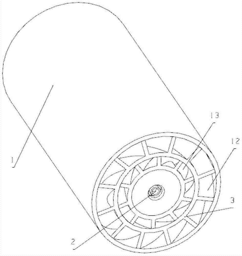

Image

  • Double-swirl dual-fuel nozzle used for chemical regenerative cycle
  • Double-swirl dual-fuel nozzle used for chemical regenerative cycle
  • Double-swirl dual-fuel nozzle used for chemical regenerative cycle

Examples


Embodiment Construction

[0016] The present invention is described in more detail below in conjunction with accompanying drawing example:

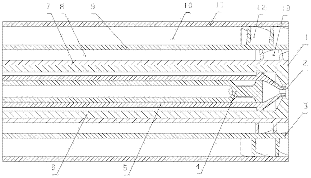
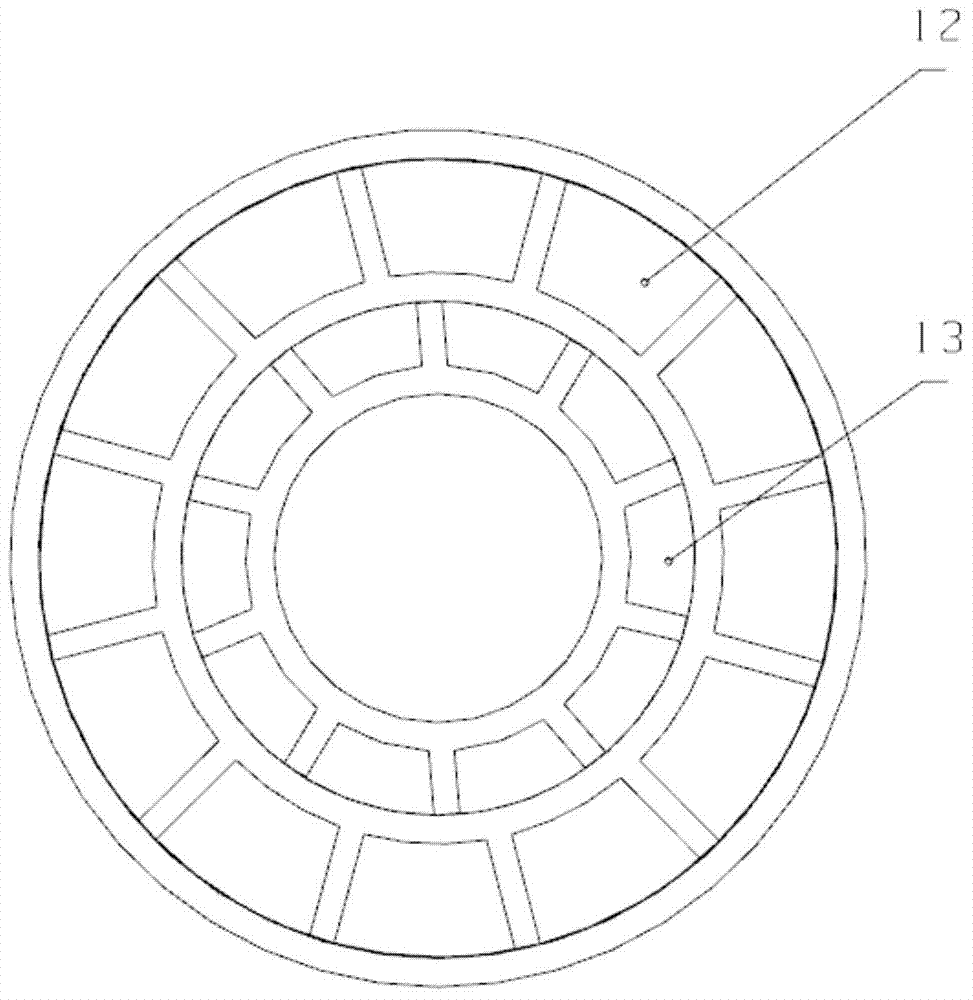
[0017] combine Figure 1~4 , the purpose of the present invention is to propose a dual-swirl dual-fuel nozzle for chemical reheating cycle, which increases the swirl degree of gas fuel through two-stage reverse swirl blades, strengthens the mixing of gas fuel and air, and strengthens the chemical Combustion in the combustion chamber in the regenerative cycle achieves the purpose of burning more fuel in a smaller space and shortening the length of the flame without causing ablation to the wall of the flame tube. At the same time, it can provide water vapor radial injection technology to ensure that the steam can be well mixed with air during reinjection, forming a humid air environment, so as to achieve the purpose of not extinguishing the fuel combustion and reducing emissions.

[0018] The dual-swirl dual-fuel nozzle 1 designed for the chemical reheating cycle i...


PUM

PropertyMeasurementUnit
Rotation angleaaaaaaaaaa

Abstract

The invention aims to provide a double-swirl dual-fuel nozzle used for a chemical regenerative cycle. The double-swirl dual-fuel nozzle comprises an auxiliary oil-path channel wall, a main oil-path channel wall, a first-level gas-path inner wall, a second-level gas-path inner wall and a gas-path outer wall, wherein the auxiliary oil-path channel wall, the main oil-path channel wall, the first-level gas-path inner wall, the second-level gas-path inner wall and the gas-path outer wall are arranged from inside to outside. An auxiliary oil-path channel is formed inside the auxiliary oil-path channel wall, and an auxiliary oil-path swirler is arranged at the end of the auxiliary oil-path channel wall and communicated with an oil-path spout. A main oil-path channel is formed between the auxiliary oil-path channel wall and the main oil-path channel wall and communicated with the oil-path spout. A first-level gas-path channel is formed between the first-level gas-path inner wall and the second-level gas-path inner wall, a second-level gas-path channel is formed between the second-level gas-path inner wall and the gas-path outer wall, the end, located on one side of the oil-path spout, of the first-level gas-path channel is provided with first-level swirl vanes, and the end, located on one side of the oil-path spout, of the second-level gas-path channel is provided with second-level swirl vanes. According to the double-swirl dual-fuel nozzle, the swirl vanes are adopted, the two levels of the swirl vanes have the opposite rotation angles, and mixing of gas fuel and air is enhanced.

Description

technical field [0001] The invention relates to a gas turbine, in particular to a nozzle of the gas turbine. Background technique [0002] A gas turbine is a typical conventional fuel power plant. It has the characteristics of small size, high power, light weight and fast start-up, and is widely used in core industrial fields such as aviation, electric power, ships and natural gas transmission. Therefore, the technical transformation and performance optimization of conventional gas turbine application technology has become an important topic to solve the energy crisis and environmental pollution problems. The chemical recuperation cycle is an advanced combustion-steam combined cycle method. It mainly uses the low-end waste heat of the gas turbine exhaust to generate superheated steam, and uses the high-end waste heat to promote the cracking of part of the fuel-steam under the action of the catalyst to generate gaseous fuels with high calorific value such as methane, hydrog...

Claims


Application Information

Patent Timeline
IPC IPC(8): F23R3/38F23R3/36
Inventor 陈曦郑洪涛潘刚刘倩潘福敏张智博
Owner HARBIN ENG UNIV
Why Eureka
Eureka Blog
Learn More