Eureka AIR delivers breakthrough ideas for toughest innovation challenges, trusted by R&D personnel around the world.

High-power semiconductor laser optical shaping method and device based on beam expanding

An optical shaping and semiconductor technology, applied in the field of laser applications, can solve the problems of small spot size compression ratio, uneven energy, short working distance, etc., and achieve the effect of increasing the size of the light-emitting surface, uniform energy distribution, and improving uniformity

Active Publication Date: 2014-07-23
FOCUSLIGHT TECH
View PDF7 Cites 26 Cited by
  • Summary
  • Abstract
  • Description
  • Claims
  • Application Information

AI Technical Summary

Problems solved by technology

[0004] 1. Reflective optical shaping method: Usually, optical waveguide can be used for optical shaping, but there is a serious depth of focus problem with this method, resulting in short working distance and unchangeable working distance;
[0005] 2. Transmissive optical shaping method: after collimating the laser light source, it is directly focused. The final output laser of this method is a flat-top spot with an interval of bright and dark phases, and the energy is not uniform; in addition, a combination of negative lens and positive lens can also be used This method of optical shaping is expensive because of the use of many lenses; in addition, the light source can be cut and rearranged before focusing, but the optical devices used in the process of cutting and rearranging are more complicated and costly. High, while the compression ratio between the light-emitting surface and the final required spot size is small, resulting in uneven output spots

Method used


Image

  • High-power semiconductor laser optical shaping method and device based on beam expanding
  • High-power semiconductor laser optical shaping method and device based on beam expanding
  • High-power semiconductor laser optical shaping method and device based on beam expanding

Examples


Embodiment Construction

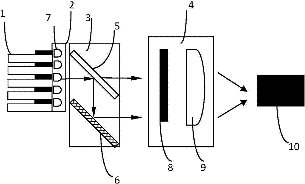
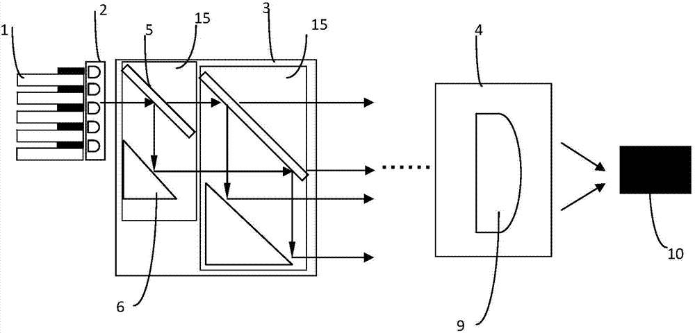
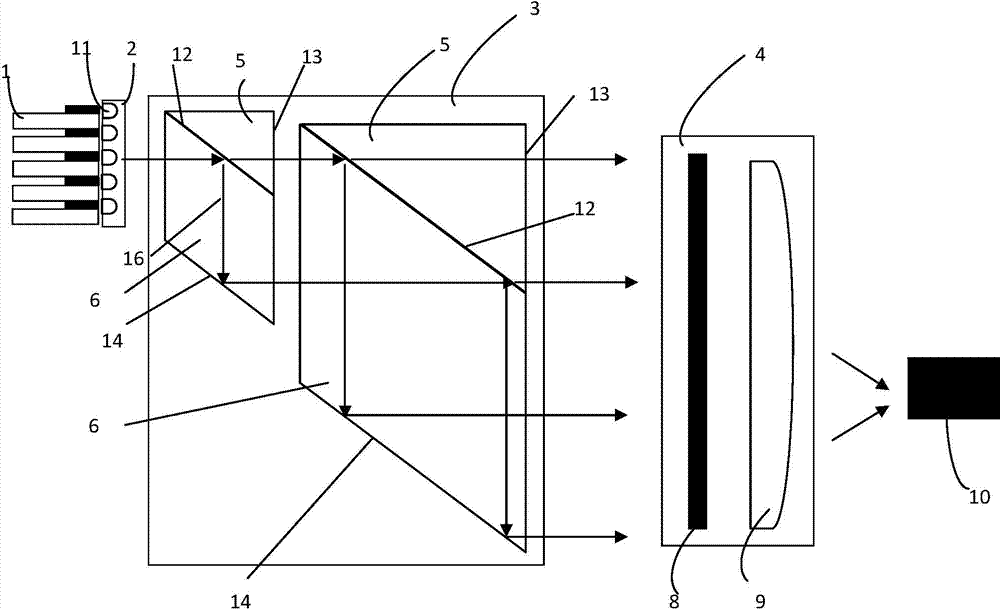
[0049] Such as figure 1 The high-power semiconductor laser optical device based on beam expansion includes a semiconductor laser stack 1, a collimating lens group 2, a beam splitting system 3 and a focusing system 4.

[0050] The semiconductor laser stack 1 is composed of several semiconductor laser units; the collimating lens group 2 is placed at the laser exit of the semiconductor laser; The collimated laser beam is expanded; the focusing system 4 is used to focus and shape the expanded laser beam.

[0051] Optical splitting system 3 includes n component optical modules, such as figure 1 As shown, in this embodiment, it is a group of optical modules, the optical module includes a beam splitter 5 and a reflector 6, and the laser light emitted by the laser is incident on the beam splitter 5; the splitting surface of the beam splitter and the reflective surface of the reflector Set parallel to each other along the height direction and form an included angle of 30-60° with the...


PUM


Abstract

The invention provides a semiconductor laser optical shaping method and device. High-power uniform light spots can be obtained, and cost is low. The principle includes that firstly, beams emitted by semiconductor laser stacks are collimated and then exponentially expanded, laser beams with energy in Gaussian distribution are transformed into flat-top beams with uniform energy density distribution, and secondly, expanded laser is focused by a focusing system, so that uniformity of the light spots can be achieved and improved.

Description

technical field [0001] The invention belongs to the field of laser applications, and in particular relates to a laser beam expander. Background technique [0002] Laser has the advantages of good monochromaticity, good directionality, good coherence and high brightness, and has been widely used in various fields of national economy. The diameter of the beam emitted by the laser is very small, usually 1-2mm. In some specific applications, such as laser processing, laser detection and laser lighting, it is necessary to use a uniform laser beam with a larger diameter. The laser is optically shaped to achieve this. [0003] Currently commonly used optical shaping methods can use the following methods: [0004] 1. Reflective optical shaping method: Usually, optical waveguide can be used for optical shaping, but there is a serious depth of focus problem with this method, resulting in short working distance and unchangeable working distance; [0005] 2. Transmissive optical shap...

Claims


Application Information

Patent Timeline
IPC IPC(8): G02B27/09
Inventor 蔡磊刘兴胜杨凯
Owner FOCUSLIGHT TECH
Why Eureka
Eureka Blog
Learn More