
An Optical Limiter with Low Clipping Threshold

An optical limiting and thresholding technology, which is applied in instruments, optics, nonlinear optics, etc., to achieve the effects of convenient operation, simple optical path and low cost

Inactive Publication Date: 2016-07-06
SOUTHEAST UNIV
View PDF4 Cites 0 Cited by
  • Summary
  • Abstract
  • Description
  • Claims
  • Application Information

AI Technical Summary

Problems solved by technology

There is no optical limiter developed based on vector beams in the prior art data

Method used


Image

  • An Optical Limiter with Low Clipping Threshold
  • An Optical Limiter with Low Clipping Threshold
  • An Optical Limiter with Low Clipping Threshold

Examples


Embodiment Construction

[0016] The present invention will be further described below in conjunction with the accompanying drawings.

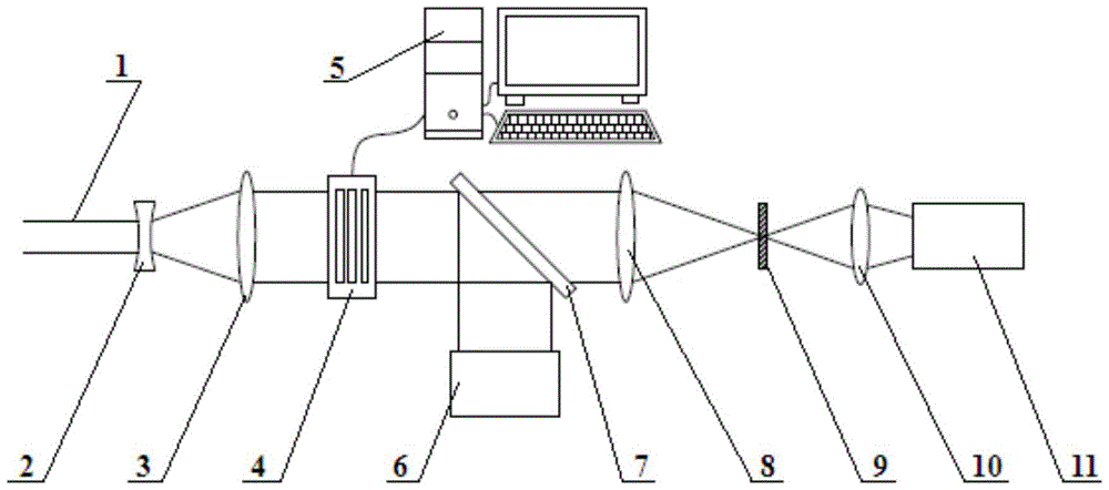
[0017] Such as figure 1 Shown is a light limiter with a low clipping threshold, including a beam expander collimator system, a radially polarized light generation system and an optical limiter system, the beam expander collimator system includes a concave lens 2 and a convex lens 3, the The radially polarized light generation system includes a liquid crystal polarization converter 4, a beam analyzer 6, and a beam splitter 7, and the optical limiting system includes a B convex lens 8, a nonlinear absorption sample 9, a C convex lens 10, and an energy detector 11, so The nonlinear absorption sample 9 is placed between the B convex lens 8 and the C convex lens 10, and is placed on the focal plane of the B convex lens 8 and the C convex lens 10; the laser beam 1 output by the laser passes through the concave lens 2 and the A convex lens 3 in sequence and then expands the b...


PUM


Abstract

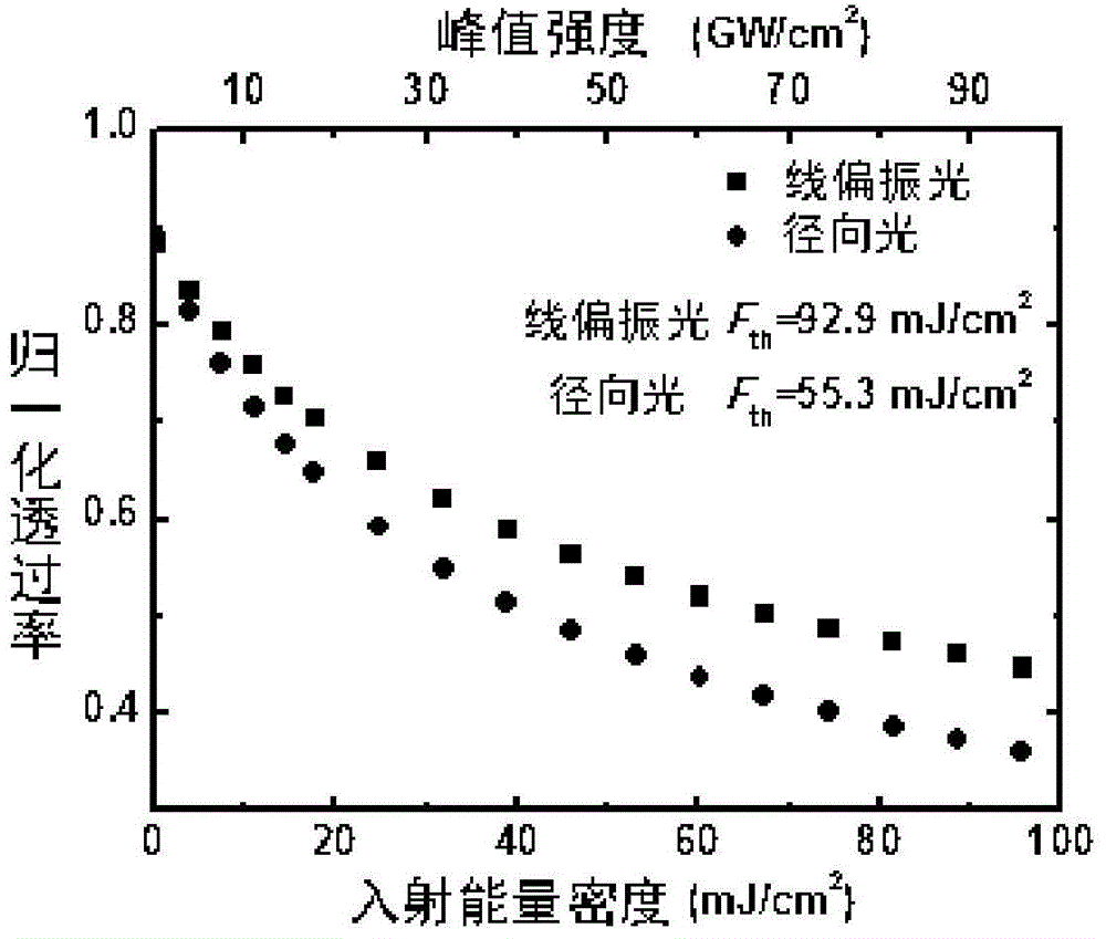
The invention discloses an optical limiter with a small limiting threshold value. The optical limiter with the small limiting threshold value comprises a beam expanding collimation system, a radially polarized beam generation system and an optical limiting system. A linearly polarized laser beam is converted into a radially polarized beam through a liquid crystal polarization converter. The laser beam is focused through a convex lens. Nonlinear absorption materials are placed on the focal plane of the lens. The light intensity of light passing through a sample is nonlinearly reduced along with increase of the incident intensity through the two-photon absorption effect of the materials, in this way, the optical limiting purposes that when the light intensity is low, the transmittance is high, and when the light intensity is high, the transmittance is low are achieved, and human eyes and optical elements are effectively prevented from being damaged by a high power laser. By the adoption of the optical limiter with the small limiting threshold value, a light path is simple, the manufacturing cost of the optical limiter is low, compared with an existing optical limiter, the limiting threshold value is reduced by about 50%, and the human eyes and optical precise instruments are more sensitively and efficiently protected from being damaged by the high power laser.

Description

technical field [0001] The invention relates to an optical limiter with a low clipping threshold, which is a laser protection optical device based on polarization state regulation, used to protect human eyes and optical components from strong laser damage, and belongs to the application technology of nonlinear photonics and The field of modern photonics. Background technique [0002] Since 1990, due to the rapid development of ultra-fast and strong laser technology, the application field of laser in the military has been greatly expanded. Technologies such as laser range finder, laser target designator, and laser guidance have made great progress, and have become indispensable and important equipment for the army. . In addition, lasers also have a huge market in civil use, and have been applied in medicine, meteorology, maritime affairs, aviation and other fields. With the wide application of laser, people pay more and more attention to its safety and protection, and it is...

Claims


Application Information

Patent Timeline
Patent Type & Authority Patents(China)
IPC IPC(8): G02F1/355G02F1/35
Inventor 顾兵吴佳騄刘达辉叶莉华崔一平
Owner SOUTHEAST UNIV
Learn More