Grid drive circuit and grid drive method

A gate drive circuit and gate drive technology, applied in the direction of instruments, static indicators, etc., can solve the problems of enlarging and occupying the boundary wiring area, and achieve the effect of reducing the boundary wiring area

Inactive Publication Date: 2014-07-23
SHENZHEN CHINA STAR OPTOELECTRONICS TECH CO LTD
View PDF12 Cites 22 Cited by
  • Summary
  • Abstract
  • Description
  • Claims
  • Application Information

AI Technical Summary

Problems solved by technology

[0004] However, a GOA cell (cell) is usually composed of several TFTs and capacitors, such as 7T2C, and the capacitors will occupy some area on the wiring. If a panel with a Tri-gate structure is used, the number of cells in the entire GOA will increase. Three times the original size will make the border wiring (layout) area of ​​the panel larger

Method used


Image

  • Grid drive circuit and grid drive method
  • Grid drive circuit and grid drive method
  • Grid drive circuit and grid drive method

Examples


Embodiment Construction

[0039] In order to further illustrate the technical means adopted by the present invention and its effects, the following describes in detail in conjunction with preferred embodiments of the present invention and accompanying drawings.

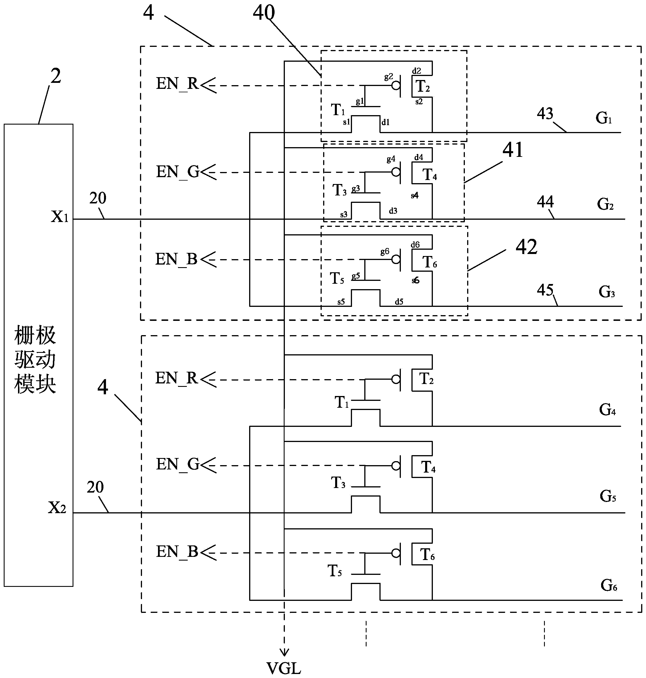
[0040] see image 3 , is a schematic circuit diagram of the first embodiment of the present invention. The present invention provides a gate drive circuit, including: a gate drive module 2 and several multiplexer modules 4 that are electrically connected to the gate drive module 2 and applied to a panel of a Tri-gate structure, wherein, The gate drive module 2 includes several signal output ports 20; wherein, the gate drive module 2 can be a GOA module;

[0041] The multiplexer module 4 includes a low level input terminal VGL, first, second and third multiplexer units 40, 41 and 42, and first, second and third signal output terminals 43 , 44 and 45;

[0042] Each of the multiplexer modules 4 has three control signals corresponding to the fi...


PUM


Abstract

The invention provides a grid drive circuit and a grid drive method. The grid drive circuit comprises a grid drive module (2 or 2') and a plurality of multiplexer modules (4 or4'). The multiplexer modules (4 or4') are electrically connected with corresponding signal output ports (20 or 20') and comprise low-level input ends (VGL or VGL') and first, second and third signal output ends (43, 44 and 45 or 43', 44' and 45'), wherein the first, second and third signal output ends (43, 44 and 45 or 43', 44' and 45') are used for being electrically connected with a panel of a Tri-gate framework. The multiplexer modules (4 or4') control the first, second and third signal output ends (43, 44 and 45 or 43', 44' and 45') to be electrically connected or disconnected with the low-level input ends (VGL or VGL') of the multiplexer modules (4 or4') or the corresponding signal output ports (20 or 20'). The invention further provides the corresponding grid drive method. According to the grid drive circuit and method, the number of Tri-gate mode grid drive devices can be reduced greatly, and the boundary wiring area of the panel can be reduced.

Description

technical field [0001] The invention relates to the field of liquid crystal display, in particular to a gate driving circuit and a gate driving method. Background technique [0002] GOA (Gate Driver on Array, array substrate row drive) technology integrates TFT (Thin Film Transistor, thin film field effect transistor) as a gate switching circuit on the array substrate, thereby saving the gate originally arranged outside the array substrate. Drive the integrated circuit part to reduce the cost of the product from two aspects of material cost and process steps. GOA technology is currently a commonly used gate drive circuit technology in the field of TFT-LCD (Thin Film Transistor-Liquid Crystal Display) technology. Its manufacturing process is simple and has good application prospects. The functions of the GOA circuit mainly include: using the high-level signal output by the previous row of gate lines to charge the capacitor in the shift register unit so that the current row o...

Claims


Application Information

Patent Timeline
Patent Type & Authority Applications(China)
IPC IPC(8): G09G3/36
CPCG09G3/36
Inventor 李冀翔
Owner SHENZHEN CHINA STAR OPTOELECTRONICS TECH CO LTD
Why Eureka
Try Eureka